Innovationsutmaning (TE18DP och TE18IM): Komma på tekniska konstruktionslösningar som lösningar på problemen med översvämningarna i Halland och Blekinge.
Varför ska vi göra det? De akuta översvämningarna ger upphov till stora materiella och ekonomiska skador och även säkerhetsrisker för miljön, människor och djur som bor i dessa områden.
Vad ska vi göra och hur? Målsättningen är att komma på flera fungerande tekniska konstruktionslösningar som kan förhindra eller minska skadorna vid framtida översvämningar i Halland och Blekinge. Vi ska arbeta med en innovationsprocess där vi utgår från autentiska case och user stories.
Sätta oss in i problemet genom att titta på problembeskrivningen.
Skaffa mer information om problemet och tänkbara lösningar genom att göra research.
Formulera fokusfrågor.
Göra en riskanalys och prioriteringslista.
Ta fram många tänkbara förslag på lösningar genom en kreativ idégenerering.
Utvärdera och välja ut de bästa förslagen.
Utveckla och konkretisera de bästa förslagen.
Presentera de konkretiserade förslagen.
Problembeskrivning
Några av våra åar svämmar över vissa år. Varje gång det sker ger översvämningarna upphov till stora materiella skador på fastigheter, vägar och miljön, men även säkerhetsrisker för människor och djur som bor och vistas på platser runt dessa vattendrag. Det sker inte varje år så det har varit svårt att planera förebyggande insatser eller göra permanenta preventiva lösningar. När det sker översvämningar så är folket och samhället inte förberedda, så de flesta hinner inte skydda sina ägor innan översvämningarna och skadorna är ett faktum. Klimatförändringarna bidrar till allt fler extrema väder vilket ökar risken för att detta ska hända oftare i framtiden. Flera av de akuta åtgärder som sätts in idag är inte effektiva och bidrar ibland till icke gynnsamma bieffekter. Det är därför angeläget att hitta nya bättre lösningar för att bättre klara av utmaningarna i framtiden.
Research och diskussionsfrågor
Skaffa mer information om problemet och tänkbara lösningar genom att göra research. Använd gärna diskussionsfrågorna nedan som utgångspunkt för din research. Läs igenom tidningsartiklarna nedan.
Varför sker översvämningarna?
Hur ofta sker det?
Hur mycket vatten handlar det om?
Vad är det som händer vid översvämningarna?
Vilka skador kan uppstå på egendom, natur, samhället och individer?
Vilka är de drabbade?
Hur brukar liknande utmaningar lösas?
Hur har man gjort tidigare?
Hur gör man idag?
Hur löser man det på andra platser, i andra länder?
Vilka aktörer är inblandade för att lösa problemen?
Vems ansvar är det att skydda egendom?
Vems ansvar är det att förebygga så att översvämningarna inte sker?
Vem är det som ska betala för skadorna?
Vem är det som ska investera i lösningarna?
Bakgrundsmaterial, tidningsartiklar och korta filmade nyhetsinslag om de aktuella översvämningarna
Risken för ras och skred ökar – var uppmärksam när vattnet sjunker undan
När det varit höga flöden och vattnet sedan börjar sjunka undan ökar risken för ras och skred. Jord, grus, sten och sand kan komma i rörelse.
När en översvämning pågår tränger vatten in i jorden i det översvämmade området. Grundvattennivån blir förhöjd och vattentrycket ökar i jordens porer (höjt portryck). När portrycket höjs försämras jordens hållfasthet.
När vattnet sedan sjunker undan, sjunker inte den förhöjda grundvattenytan av i samma takt. Särskilt långsamt sjunker grundvattenytan undan i täta, finkorniga jordar som lera och silt. Siltjord har så små korn att man inte kan urskilda dem med ögat.
Om dessutom en tung vall har lagts ut för att förhindra översvämningens utbredning, tillkommer även vallens vikt som en pådrivande faktor.
Vilka tecken på jordskred kan jag hålla utkik efter?
Färska erosionsskador i slänter mot vattendrag.
Plötsliga sprickor och sättningar i marken.
Brott på ledningar och kablar i marken.
Träd och stolpar som börjar luta.
Fokusfrågor
Hur kan vi minimera skadorna från översvämningarna när de väl sker?
Hur kan vi begränsa översvämningarna på de mest känsliga platserna (t ex vid viktiga vägar, broar, hus, byggnader)?
Hur kan vi med hjälp av digitalisering och modern teknik som t ex IoT, internetuppkopplade sensorer, webbtjänster och appar skapa lösningar för att hjälpa oss att hantera, reagera på, styra och förhindra översvämningarna?
Riskanalys
Vad kan hända vid dessa översvämningar? Vilka skador kan uppstå på egendom, natur, samhället och individer? Vilka är de mest prioriterade riskerna?
Ta fram förslag på lösningar
Ta fram många förslag på tänkbara lösningar på hur man skulle kunna lösa utmaningarna i fokusfrågorna ovan. Använd en kreativ idégenereringsprocess och brainstorming i första steget.
Jobba enskilt tyst och skriv upp så många förslag du kommer på.
Jobba i grupper (samma grupper som i Fashiontech-projektet). Utse en i gruppen som sammanställer allas idéer i en gemensam lista som alla får ta del av.
Bygg vidare på varandras idéer. Kom på ännu fler idéer, kanske nya kombinationer av flera förslag. Här är även elever från TE18IM som läser Dator- och Nätverksteknik, Ciscos IoT-kurs, Webbutveckling och Programmering med i projektgrupperna för att få in förslag på digitala lösningar.
Utvärdera era idéer. Vilka är akuta lösningar? Vilka är förebyggande proaktiva lösningar? Vilka idéer är mest realistiska och genomförbara? Vilka idéer tror ni har bäst effekt på att lösa problemen? Vilka anser ni borde prioriteras?
Välj ut de tre bästa idéerna/förslagen som ni i gruppen vill bygga vidare på, utveckla och konkretisera. Låt alla i gruppen vara med och rösta på alla förslagen (topp 3).
Presentera och beskriv era tre bästa förslag för de andra projektgrupperna.
Utveckla och konkretisera ert bästa förslag
Konkretisera ert bästa förslag från igår gällande lösningar mot översvämningarna.
Jobba tillsammans i projektgruppen
Dela upp ansvarsområden så att alla i gruppen får en uppgift och arbetar.
Ni ska konstruera er lösning. Hur ska den se ut? Var ska den installeras? Hur ska den byggas? Vilka material och delar ska den bestå av? Vilka krafter kommer den utsättas för och vad krävs för att den ska hålla och fungera?
Ta fram en prototyp eller modell. Skapa en skiss eller 3D-modell på hur den ska se ut. Bygg en fysisk modell eller prototyp. Använd material vi har i Makerspace för att konstruera och bygga er modell.
Implementering
Presentation av idéerna, förslagen och modellerna för Region Halland, MSB, Räddningstjänsten, företag och de kommuner som är mest berörda. Eventuellt en artikel om arbetet och förslagen i media. Hur vill ni presentera era idéer?
De senaste åren har det skrivits mycket om att robotar tar människors jobb. Allt fler arbetsuppgifter ersätts av robotar, och fler står på tur i takt med att robotarna snabbt blir bättre och mer avancerade.
I robotiseringens och automatiseringens kölvatten skapas dock mängder av nya arbetstillfällen, främst inom teknikyrken som programmering, AI och mekatronik.
Här är dock ett intressant filmklipp från Japan som visar hur ett café erbjuder människor med funktionsnedsättningar arbetstillfällen som robotservitörer. Robotarna i caféet fjärrstyrs helt enkelt av människor som kan sitta eller ligga hemma och styra dem och interagera med caféets besökare. Mänsklig social interaktion och social integrering möjliggörs tack vara robotarna.
Robotar som ger människor jobb
Uppgifter och diskussionsfrågor
Vad tycker du om det du såg på filmen? Hur känner du inför en utveckling där allt fler mänskligt fjärrstyrda robotar interagerar med oss i offentliga miljöer som t ex caféer eller butiker?
Ge exempel på negativa saker med mänskligt fjärrstyrda robotar som interagerar med oss i offentliga miljöer.
Ge exempel på positiva saker med mänskligt fjärrstyrda robotar som interagerar med oss i offentliga miljöer.
Tycker du att denna typ av arbetsuppgift enbart ska utföras av människor med olika typer av funktionsnedsättningar? Eller bör det vara som vilken typ av jobb som helst att alla får konkurrera om jobben på lika villkor?
Skulle du hellre vilja bli serverad av en mänskligt fjärrstyrd servitörsrobot eller en autonom robot som styrs automatiskt av artificiell intelligens eller utifrån förprogrammerade instruktioner?
Hur tycker du att en servitörsrobot ska se ut? Ska den likna roboten i filmen? Ska den likna en människa mer? Tycker du att den ska se helt annorlunda ut och kanske vara mer anpassad för att hämta och lämna brickor eller tallrikar och glas? Beskriv, skissa och sök gärna efter inspiration på Internet.
Vilka egenskaper behöver en bra servitörsrobot ha? Vad ska den kunna göra? Beskriv funktionerna och hur den rent mekaniskt ska vara uppbyggd. Vilka funktioner behöver programmeras? Vilka funktioner behöver fjärrstyras? Hur kan man lösa de olika funktionerna rent tekniskt?
Skulle du kunna tänka dig att jobba med denna typ av teknologi själv? Hur då i så fall? Som den som styr roboten, som den som programmerar den eller som den som konstruerar och designar den här typen av robotar?
Uppkopplade sensorer, s k Internet Of Things (IoT) blir allt vanligare och ger gamla traditionella produkter helt nya funktioner och möjligheter. Även kläder har på senare år klivit in i segmentet av högteknologiska produkter i och med modebranschens transformation mot fashiontech. I detta inlägg ska vi titta närmare på hur en löparsko som försetts med inbyggda sensorer och trådlös uppkoppling till mobiltelefon kan förändra användarupplevelsen och tillsammans med en tillhörande mobilapp kan ge realtidsfeedback och coacha dig så att du lär dig springa effektivare och bättre. Altras designfilosofi skiljer sig lite ifrån andra traditionella skotillverkare. Du kan läsa mer på sidan Varför Altra. För den här modellen har de valt att implementera den nya tekniken i en skomodell som även går att köpa utan tekniken. Se uppgifter och diskussionsfrågor längst ner på denna sida.
Atra Torin IQ – nya generationens löpsko
Altra Torin IQ
En intelligent löpsko och din nya löpcoach
Altra Torin IQ – smart uppkopplad löpsko med coachande mobilapp
Altra IQ Torin är en intelligent löpsko som coachar och ger feedback med hjälp av steganalys. Skon är utrustad med IoT-teknologin som kommunicerar med träningsklockan eller telefonapplikationen från iFit. Du får live feedback och löptips rakt I din klocka eller telefon medan du rör på dig. Skon mäter kollisionskrafter i sulans olika delar vilket hjälper att hitta en mer balanserad löpning. Du får information om sulans träffpunkt med marken vilket ger möjligheten att följa hur löpsteget ändras under loppet. Idén är att främja ett effektivt och hälsosamt löpsteg. Skon mäter också stegfrekvens som är en indikation på löpformen och hjälper till med att upprätthålla en önskad stegrytm i löpningen.
Altra Torin IQ – reklamfilm
Teknologi
Högteknologisk löparsko som synkroniserar med iFit®-klockor, Android eller Apple. Ingen nivåskillnad tå-häl, snabbtorkande mesh i ovandelen och bekväm dämpning.
• Applikation till iphone, Android, Google play • Trådlös kommunikation till skosensorn • Dolda sensorer inbäddade i mellansulan • Registrering av landningszon • Trycksensorer i sulans olika delar • Löptips under löpningen från appen • Realtids löpdata via IQ applikationen och analys • Du kan även följa med tid, distans och hastighet
Altra IQ är den första högteknologiska löparskon som mäter stegfrekvens, tryckbelastning och löparstil. Perfekt för den som vill analysera sin löpning.
Altra Torin IQ – smart uppkopplad löpsko med coachande mobilapp
Under innersulan sitter en trycksensor som synkroniserar trådlöst med iFit®-klockor, Android eller Apple. Den här sensorn ger dig feedback i realtid under löprundan, antingen på displayen eller genom ljudsignaler. Detta hjälper löparen att förbättra sin löpstil, fotisättning och frekvens under löprundan.
Altra Torin IQ har trycksensorer, accelerometrar och trådlöst uppkopplade microcontrollers inbyggt i varje sko.
Ovandel i slitstark, snabbtorkande Airmesh som både ger ökad ventilering och komfort. FootShape™ tåbox ger tårna extra plats att sprida ut sig för bättre komfort, stabilitet och hastighet.
Mellansulan är lätt dämpad med A-Bound™ som ger energirespons i varje steg och en heldämpad Zero Drop-plattform ger stötdämpning och en mer naturlig löprörelse. InnerFlex™ gör skon mer flexibel i mellansulan.
Specifikationer:
– Ovandel: Snabbtorkande mesh – Innersula: 6 mm Contour – Mellansula: Dual Layer EVA med A-Bound™ Top Layer & InnerFlex™ – Plattform: Natural Foot Positioning: FootShape™ Toe Box med heldämpad Zero Drop™ Platform – Yttersula: FootPod – Vikt herr: 230 g – Vikt dam: 184 g – Sulans höjd: 24 mm – Nivåskillnad tå-häl: 0 mm
Teknologi:
– Trådlös kommunikation – Mätning av fotisättning – Trycksensor – Löptips genom ljudsignaler längs vägen – Statistikregistrering – Spårning av loppet i efterhand
Användare: Herr eller Dam (olika skomodeller)
Löpunderlag: Asfalt
Pronation: Neutral
Stabilitet: ¡
Löpkänsla: ¡
Underlag: Asfalt
Stabilitet: Neutral
Dubbar: Nej
Drop: 0 mm
Vattentät: Nej
Ovandel: Fast Drying Mesh, FootShape
Mellansula: Dual Layer EVA with A-Bound, Top Layer & Innerflex
Dämpning: Full Cushioning Zero Drop Platform
Yttersula: Footpod
In this video, Brian Beckshead, President and Co-Founder of Altra, provides a look at the IQ Technology and why it can help you run better.
Lite mer information om Altra Torin IQ, tankarna bakom designen och beskrivning av funktionerna hittar du i följande engelska text från en artikel med en intervju av grundarna av Altra:
”For too long, the two main metrics to measure your run have been ’how far?’ and ’how fast?'” said Altra president and co-founder Brian Beckstead. ”With Altra Torin IQ shoes, you get a much richer picture of your run with real-time coaching. We analyze the problems in real time, and provide you with proactive suggestions so you can correct and improve right away. Running has never been smarter.”
Altra Torin IQ powered by iFit is the first and only shoe on the market to feature full-length, razor-thin, featherweight sensors and transmitters embedded in the midsole of each shoe — providing runners with live data for each foot individually. Using Bluetooth technology, the shoe communicates directly with the Altra IQ iFit app on the runner’s smartphone to continuously transmit data in four key areas: landing zone, impact rate, contact time and cadence. The app also tracks pace, distance and time.
During the run, Altra Torin IQ serves as a stride coach, relaying real-time feedback in two ways: through the app screen and audible coaching. Runners have the ability to customize how often to receive live coaching based on their preferences.
”Many running injuries can be prevented by learning efficient, low-impact running form. However, it can be really hard to analyze running form on yourself,” said Altra founder Golden Harper. ”This shoe is designed to help make runners more efficient and to extend the running career of road and trail warriors out there. Intelligence is power, and Altra Torin IQ can provide insights like nothing else.”
”The coolest thing to me is that we are able to give runners coaching tips in their moments of greatest need,” Harper continued. ”For example, as a runner’s form starts to slip near the end of a race, the IQ shoe will recognize that and give them coaching tips to get them back on the right track.”
Both Harper and Beckstead agree the Altra Torin IQ shoe is an excellent training tool for a range of runners, from beginners who want to avoid bad habits, to elites who want to fine tune their form.
Altra Elite Athlete Zach Bitter has logged hundreds of miles testing Altra Torin IQ, including training for his American record 100-mile time of 11:40:55, set at the 2015 Desert Solstice Invitational. Bitter logs 120 to 140-mile weeks during training. His next major race is the legendary Western States Endurance Run in July in California.
”The beauty of the Altra IQ technology is its variety of uses. It’s quick and accurate workout feedback can be applied right on the spot, with coaching tips that help correct problems rather than just telling you that you’re doing something wrong,” Bitter said. ”As a high-mileage runner, I think one of the coolest aspects is the information I learn about how my stride is affected over distance, through injury, sore muscles and such,” Bitter said. ”Many variables affect your training, so having baseline data of what you typically do while healthy and being able to spot-check that during a race is invaluable.”
Altra IQ powered by iFit app specs:
Landing Zone:
Landing zone helps runners avoid extremes such as landing with a harsh heel strike or too far forward on the toes. The Altra IQ app reports landing zone feedback with audio tips, as well as visual feedback on the app screen to give runners a clear idea of where each foot is hitting the ground.
”Our goal is not to change a runner’s foot strike, but instead to provide them with the tools to understand a proper foot strike is the result of having proud posture, compact arms and a high cadence — all the things we’ve been teaching in our Run Better clinics since Altra was founded,” Harper said.
Therefore, live coaching tips included in the Altra IQ app guide runners to make changes to their posture, arms, or cadence that lead to a low-impact landing. For example, if the runner is over-striding, or landing on their toes, they’ll receive an audio coaching tip that will help correct and optimize their landing.
”We’re hoping to guide runners into a ’safe zone.’ As each runner is different, their individual landing zone may vary between a soft heel landing and a slight forefoot landing,” Harper said. ”In general, the goal is to avoid the extremes of landing as a means of reducing injury and stress on the body.”
Impact Rate:
Altra Torin IQ’s dual sensors monitor how hard each foot hits the ground and identifies left–right imbalances in their stride, for a metric Altra calls ”impact rate.” Coaching guidance from the app helps runners land more softly and achieve more balance, which may lead to a lower likelihood of injury. Altra IQ reports impact rate in two ways: a number expressed in millig-units (mG) and as a visual on the app screen showing how balanced the runner is.
”The practical application of impact rate will be during a run or race where pace is generally constant,” said Harper. ”As a runner loses form, their impact rate may increase. Therefore, monitoring impact rate during a run or race is an excellent way to ensure efficient form. As an example, an individual running at a constant pace with poor form will have a higher impact rate number than they would at the same pace with efficient form.”
Harper added, ”As runners increase speed, impact rate will naturally increase, even when running with efficient technique. The goal is for runners to maintain a consistent impact rate number while running at a given pace.”
Contact Time:
Running performance is contingent on many variables, and ground contact time is one of the lesser known. Altra IQ contact time data shows runners how much time each foot is in contact with the ground and is reported as a number of milliseconds (ms), with a separate score for each foot. With this data, runners can improve left-right balance and optimize contact time.
”Lower contact times are often associated with a higher cadence and more efficient, lower impact foot strikes,” Harper said. ”Additionally, a left-right imbalance may serve as a clue revealing a current, past, or forthcoming injury.”
Cadence:
Cadence is the live ”pulse” of a run and a key factor in form, foot strike and efficiency. Altra Torin IQ’s live cadence tracking provides data to keep foot turnover at the optimal rate for the current running pace, helping runners become more fluid. Altra IQ powered by iFit reports cadence as a number of total steps per minute. In general, working up to a higher cadence in the 170 to 180 range improves running form and efficiency.
Uppgifter och diskussionsfrågor
Har du sett någon liknande produkt med motsvarande funktionalitet tidigare? Vilken i så fall?
Vilka liknande produkter med motsvarande funktionalitet hittar du nu om du Googlar?
Ge exempel hur de liknar varandra och vad som eventuellt skiljer dem åt.
Vilka komponenter behövs för att göra en vanlig löparsko till en smart sko med samma funktioner som Altra Torin IQ?
Vilka yrkeskategorier och vilken kompetens behövs för att designa och konstruera en smart sko som Altra Torin IQ?
Ge exempel på några andra produkter som inte är ”smarta skor” men som har liknande funktionalitet eller kan ge motsvarande information om din löpning.
Om du skulle designa och konstruera en smart löparsko idag, vilka funktioner skulle du då satsa på?
När Altra Torin IQ lanserades år 2017 var de först i världen. Hur vanligt tror du att det kommer vara med smarta uppkopplade löparskor år 2025?
Hur innovativ anser du att Altra Torin IQ var som produkt när den lanserades 2017 (1-5, där 1 = inte innovativ alls, 2 = lite innovativ, 3 = ganska innovativ, 4 = innovativ, 5 = mycket innovativ)?
I Sverige slänger vi i genomsnitt knappt åtta kilo kläder i soporna varje år. En hel del av dem skulle kunna återanvändas men än så längre saknas bra metoder, framför allt för återvinning i större skala. Men det pågår flera projekt för att ta fram sådana metoder. Ett av dem är projektet WargoTex Development som startade 2018 i Vargön utanför Vänersborg och ska pågå i två år.
– Mycket textil återanvänds inte därför att det saknas bra funktioner för sortering, säger Maria Ström, verksamhetsledare på Wargön Innovation som driver projektet.
Maria Ström,. verksamhetsledare Wargön Innovation.
Utvecklingsprojektet, som fått stöd av Energimyndigheten, samlar 25 samarbetspartner under ett tak. Bland dem högskolor, kommunala energibolag, välgörenhetsorganisationer, återvinningsföretag och klädkedjor.
– Vi vill förstå hur man kan sortera textilierna mer effektivt. Vi har fått lokaler med en processhall där vi ska testa olika saker. Vi har fem demoprojekt, bland dem ett som tittar på robotteknik och ett som håller på med industriell redesign, säger Maria Ström.
Behövs industriell kapacitet
Projektet kom enligt henne till därför att flera olika aktörer inom återvinning hade nya idéer om vad man kan göra med uttjänt textil, men de hade insett att det i Sverige saknas industriell kapacitet för textilsortering.
– Vi såg en lucka just i sorteringsfunktionen. Om ett stort företag ser att de skulle kunna göra en produkt med återvunnen textil, då kanske de vill ha 10 000 ton på ett år, men den volymen finns inte framme i dag, säger hon.
I sorteringen gäller det att skilja ut de textilier som kan återanvändas – till exempel klädesplagg – från de uttjänta som ska återbrukas, det vill säga förvandlas till ny textilråvara eller annan råvara.
Råvaran måste sorteras
– Får man in en stor hög med textilier kan där finnas allt från urtvättade barntröjor till Armanikostymer. Det pågår många projekt inom det här området, det finns till exempel minst två svenska projekt som arbetar med att separera bomull och polyester. Men allt kräver att det finns en sorterad råvara, säger Maria Ström.
I stället för att brännas kan de begagnade plaggen återanvändas eller återvinnas. Foto: Jerry Lövberg
Det finns många aktörer som arbetar med återvinning och återbruk av textilier på olika sätt. Därför är det så många olika samarbetspartner med i projektet i Vargön – alla kan bidra med sina erfarenheter och kunskaper.
– Vi behöver också utveckla textilinsamlingen. Andra länder, som Tyskland, Frankrike och våra nordiska grannländer samlar in mer än vi. Alldeles för mycket textil slängs fortfarande, säger Maria Ström.
”En utmaning för oss som medborgare”
Hon framhåller att vi i Sverige har en hög konsumtion av kläder.
– Mycket blir bara liggande, ibland utan att man ens tagit bort prislappen. Det här är en utmaning för oss som medborgare – att handla mer second hand, vara rädda om våra kläder, lämna ifrån oss det vi inte använder.
Design- och konstruktionsuppgift: (Kurser: Design 1, Konstruktion 1, Teknik 1, Uppfinnarresan)
Uppfinn en fungerande klädsorteringsmaskin.
Vad behöver maskinen kunna göra? Förklara och beskriv sorteringsprocessen steg för steg.
Skapa en funktionsbeskrivning som förklarar hur sorteringsanläggningen eller din maskin fungerar och vilka delar den består av.
Designa, skissa, rita och konstruera en modell eller prototyp.
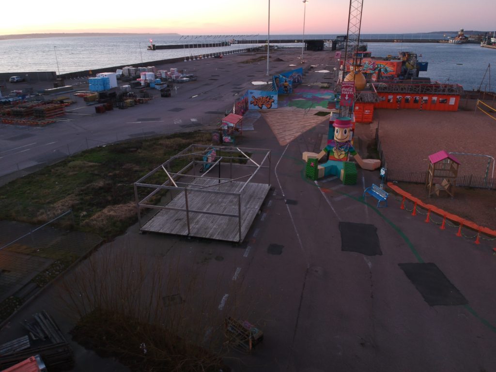
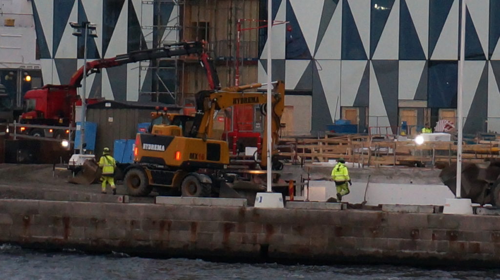
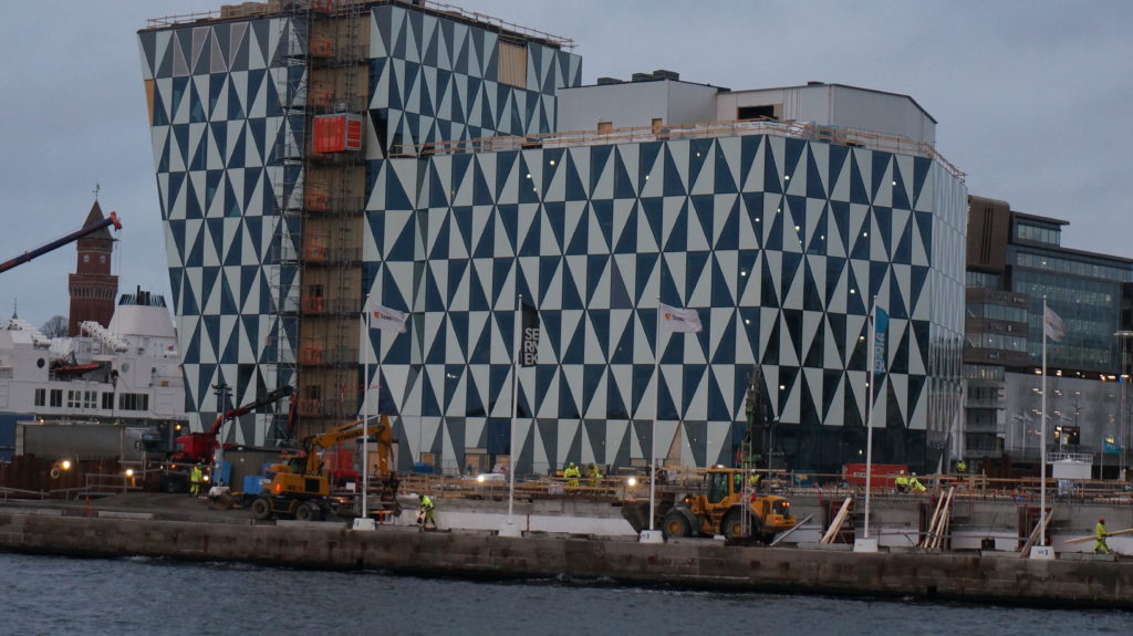
Drönarfoto över Oceanhamnen och Pixlapiren 22 januari 2020
Det händer mycket i Oceanhamnen i Helsingborg nu. Oceanhamnen är första etappen av stadsutvecklings-projektet H+ i Helsingborg som fram till år 2035 ska omvandla en miljon kvadratmeter gammalt hamn- och industriområde till de fyra stadsdelarna Oceanhamnen, Universitetsområdet, Husarområdet och Gåsebäck och ge plats för 10 000 nya invånare. Syftet är att skapa framtidens smarta hållbara stad och då behöver vi självklart involvera eleverna på Innovationsgymnasiet i Helsingborg!
Alla viktiga projekt behöver en flygande start! Först ut på bollen är teknikeleverna i årskurs 2 (TE18DP) som läser Design, Konstruktion, CAD och produktutveckling som, förutom att skapa 3D-ritningar med inredningsförslag till blivande bostadsrätter, kontor och hotell, även kommer bygga fysiska 3D-modeller av de nya bostäderna. Teknikeleverna i årskurs 1 (TE19) är också med i projektet och kommer jobba med fasadritningar och bygga skalenliga modeller av fastigheternas fasader inom kursen Teknik 1. TE18DP ska även designa och konstruera förslag på smarta, kompakta och mobila modulära studentbostäder av återbruksmaterial. Som en naturlig del i projektet väver vi in innovativa tekniska lösningar för smarta hem, intelligenta byggnader med lokal energiåtervinning och system för användarcentrerad feedback i syfte att minska varje individs energi- och vattenförbrukning och avfallsmängd. För de projekt och produktidéer som rör IoT (Internet Of Things) och digitala lösningar kommer våra elever (TE18IM) som läser Dator- och Nätverksteknik, Programmering, Webbutveckling och certifieringskursen Cisco IoT Fundamentals Connecting Things involveras. Genomgående för uppdragen är tillämpning av principer för hållbar design och användandet av moderna professionella digitala design- och konstruktionsverktyg som Blender, Sketchup, Fusion 360, Meshroom, Autodesk Revit, Unity, Unity Reflect samt 3D-skrivare och återbruksmaterial för att skapa skalenliga fysiska modeller. Under våren kommer natureleverna (NA19), som en del av projektet ”TIS-Tema Vatten”, titta närmare på den nya innovativa vattenreningsanläggningen Reco Lab (se mer info nedan) som är en modell för framtidens avloppssystem som håller på att byggas i Oceanhamnen.
Oceanhamnsområdet är just nu en inhägnad byggarbetsplats där förvandlingen till en levande stadsdel med de första 450 bostäder pågår för fullt så att de första invånarna kan flytta in redan nästa år. Här byggs också restauranger, handelsyta och Oceanhamnen Waterfront Business District, ett nytt affärsdistrikt med 32 000 kvadratmeter nya kontor. Området får endast besökas av behörig personal med ID06 passerkort, så vi har inte möjlighet att gå dit och göra fältstudier på nära håll med eleverna. Så för att få en inblick i hur arbetsprocesserna och bygget fortskrider får vi ta till andra kreativa metoder. I första hand söker vi samarbeten med de aktörer som är inblandade i olika delar av Oceanhamnen-projektet.
För att få lite perspektiv på projektet, fågelperspektiv alltså, så lyfte jag blicken och flög runt ett par varv och kollade in hur området ser ut idag, den 22 januari 2020. Här nedan är ett litet filmklipp med en helikoptervy över området som vi kommer ha under luppen de närmaste månaderna.
För att få en känsla för hur det är tänkt att se ut när Oceanhamnen är färdigbyggd så är en 3D-visualisering med realistisk rendering ett bra och kraftfullt verktyg. Här nedan får du en förhandstitt i 3D på den nya stadsdelen som håller på att växa fram med ett spektakulärt läge vid havet, ett stenkast från Helsingborgs centralstation. För att skapa en sådan film kan man t ex använda programvaran Blender 2.81 som vi börjat använda i kurserna Design, Konstruktion och Cad.
Välkommen till Oceanhamnen – 3D visualisering (3:05)
Digitalisering möjliggör nya innovativa arbetssätt Om man vill gå ett steg längre och erbjuda en interaktiv upplevelse så att besökaren själv kan navigera runt i 3D-miljön så kan man istället lägga in de 3D-objekt man skapat i t ex Fusion 360 eller Sketchup, i spelutvecklingsmiljön Unity, som vi använt i undervisningen i Programmering. I Unity kan man även skapa en interaktiv VR- eller AR-upplevelse. Med Unity Reflect kan man sedan koppla samman konstruktionsritningarna och projektplaneringsverktygen och följa hela byggprocessens alla olika steg i VR från en annan plats, eller med hjälp av AR-teknik se hur byggnaden steg för steg kommer att byggas upp precis där du står, trots att det ännu inte är klart. Det är som att i realtid kunna se in i framtiden, in genom väggar eller tillbaka till hur någonting såg ut innan.
Unity Reflect gör konstruktionsdokument och ritningar digitalt tillgängliga på byggarbetsplatsen i realtid via AR.
Här kan du se var byggherrarna bygger
Det är totalt sex byggherrar som ska bygga bostäder i den nya stadsdelen. Vi vill gärna samarbeta med dem på olika sätt inom ramen för de kurser eleverna läser, men även för SYV (Studie- och Yrkes-Vägledning). Det kan t ex handla om studiebesök, intervjuer, designuppdrag eller praktikplatser. Kartan härunder visar var de ska bygga, och länkarna går till mer information om dem och deras projekt.
Översiktskarta över Oceanhamnen med markeringar för placeringen av de olika byggherrarnas bostadsfastigheter.
Oceanpiren är en del av Oceanhamnen, ett nytt spännande bostadsområde mitt i Helsingborg. På bästa läge, längst ut på piren, bygger vi 69 bostadsrätter om 1-4 RoK – Brf Oceanpiren. Här bor du på första parkett vid havet, i hjärtat av stadsdelen, i ljusa, välplanerade bostadsrätter som är byggda för en hållbar livsstil. Samtidigt om vi uppför Brf Oceanpiren bygger vi fyra radhus i townhouse-stil. Vi kallar dem Oceanvillorna. De har både hållbarhetstänket och den magnifika havsutsikten gemensamt med Brf Oceanpiren.
Design-, konstruktions- och CAD-uppgifter till TE18DP Här är en lista på exempel på arbeten och uppdrag som eleverna ska jobba med. Mer utförliga och detaljerande instruktioner ges under lektionerna, men de olika uppgifterna publiceras också på sidorna Designuppgifter för TE18DP och Konstruktions- och CAD-uppgifter för TE18DP.
Skapa en CAD-ritning på en av lägenheterna i Brf Oceanpiren. Utgå från planritningen.
Skapa ett komplett inredningsförslag till lägenheten.
Skapa konstruktionsritningar av väggsektioner, tak och golv i minst två olika material.
Skapa en materiallista och kostnadskalkyl för de ingående konstruktionselementen.
Gör hållfasthetsberäkningar och riskanalyser
Jämför materialalternativen med hänsyn till kostnad, hållfasthet, hållbarhet, miljöpåverkan, klimatavtryck och möjlighet till återvinning (livscykelanalys).
Oceanvillorna
De townhouse-inspirerade Oceanvillorna är Oceanpirens mest fulländade boende med spektakulära solnedgångar och en magnifik havsutsikt
World Trade Center Helsingborg i Oceanhamnen ska bli mötesplatsen för entreprenörer, scale-ups, etablerade företag och affärs- och helgresenärer.
World Trade Center med Scandic Hotel Helsingborg på Bröderna Pihls gränd
WTC Helsingborg blir en kontors- och hotellfastighet som kommer bli ett landmärke i Helsingborg. Med sina fjorton våningar precis vid hamninloppet ger den dig närkontakt med sundet, båtarna och kontinenten. Här kommer finnas gemensam service som reception och konferensavdelning. Gym, relax, dusch- och omklädningsrum. Restaurangen med uteservering vid vattnet och takterasser är ytterligare fördelar som berikar både arbets- och privatliv. I källaren planeras för cykelgarage med möjligheter till reparationer och en laddstation för elcyklar.
Fastighet är ritad av Juul Frost Arkitekter, men byggherren Midroc välkomnar kunderna tidigt in i processen för att kunna påverka lokalens utformning så att den passar verksamheten bäst. Att vara med och arbeta med förslag på lokalernas utformning kan vara ett bra elevprojekt! Juul Frost Arkitekter är förövrigt experter på design av campusområden och studentbostäder, och hur man kan integrera dem i städer.
Oceanhamnen får ett innovativt nytt avloppssystem– Reco Lab med Tre Rör Ut
Innovativt avloppssystem i Oceanhamnen kräver nytänk (2:13)
Oceanhamnen kommer få en helt ny typ av klimatsmart avloppssystem med värmeåtervinning och lokalt producerad biogas. Varje fastighet ansluts till tre separata rör, ett för matavfall, ett för gråvatten och ett för svartvatten. Detta innovativa avloppssystem kräver att ingenjörerna tänker utanför boxen. I filmklippet ovan berättar VA-ingenjören Peter Winblad på Nordvästra Skånes vatten och avlopp, NSVA, om utmaningarna.
Reco Lab – en testbädd och showroom för framtidens källsorterande avloppssystem
Reco Lab kommer att bidra till att utveckla det världsunika systemet Tre Rör Ut för insamling och hantering av mat- och toalettavfall i fastigheterna på Oceanpiren i stadsdelen Oceanhamnen i centrala Helsingborg.
På uppdrag av NSVA har entreprenörföretaget NCC upphandlat det nederländska företaget Landustrie och det svenska företaget EkoBalans Fenix AB för att installera processteg i det unika Reco labs utvecklingsanläggning. Reco lab, som är en del av Öresundsverket i Helsingborg, ska behandla det källsorterade avloppet från Helsingborgs nya stadsdel, Oceanhamnen. Avloppshantering har en naturlig roll att spela i den cirkulära ekonomin då mycket av våra essentiella resurser, som vatten, näringsämnen och organiskt material passerar igenom stadens avlopp.
Det källsorterande avloppet innebär en reningsprocess med kraftigt ökad resursåtervinning. Miljövinsterna är flera:
ökad biogasproduktion
ökad näringsåtervinning
effektiv värmeåtervinning
mer energieffektiv läkemedelsrening
minskad klimatpåverkan
möjligheten för vattenåtervinning
Reco Lab planeras att vara färdigbyggt och driftsatt våren 2021 och inkluderar även ett showroom för utbildning samt en testbädd för teknikutveckling. Studiebesök hos NSVA för natureleverna (NA19) är planerat till maj 2020. Eleverna i NA18 borde också studera Reco Lab som en del av biologi- och kemikurserna, i synnerhet de som valt inriktningen mot natur och samhälle.
Bilder på bygget av Oceanhamnen
Bilder från fältstudie vid Oceanhamnen och Pixlapiren 2020-01-22 med drönaren DJI Spark:
DCIM/100MEDIA/DJI_0307.JPG
DCIM/100MEDIA/DJI_0309.JPG
DCIM/100MEDIA/DJI_0310.JPG
DCIM/100MEDIA/DJI_0311.JPG
DCIM/100MEDIA/DJI_0312.JPG
DCIM/100MEDIA/DJI_0314.JPG
DCIM/100MEDIA/DJI_0315.JPG
DCIM/100MEDIA/DJI_0316.JPG
DCIM/100MEDIA/DJI_0317.JPG
DCIM/100MEDIA/DJI_0319.JPG
DCIM/100MEDIA/DJI_0320.JPG
DCIM/100MEDIA/DJI_0321.JPG
DCIM/100MEDIA/DJI_0323.JPG
DCIM/100MEDIA/DJI_0325.JPG
DCIM/100MEDIA/DJI_0326.JPG
DCIM/100MEDIA/DJI_0327.JPG
DCIM/100MEDIA/DJI_0328.JPG
DCIM/100MEDIA/DJI_0329.JPG
DCIM/100MEDIA/DJI_0330.JPG
DCIM/100MEDIA/DJI_0331.JPG
DCIM/100MEDIA/DJI_0332.JPG
DCIM/100MEDIA/DJI_0334.JPG
DCIM/100MEDIA/DJI_0335.JPG
DCIM/100MEDIA/DJI_0336.JPG
DCIM/100MEDIA/DJI_0338.JPG
DCIM/100MEDIA/DJI_0339.JPG
DCIM/100MEDIA/DJI_0340.JPG
DCIM/100MEDIA/DJI_0342.JPG
DCIM/100MEDIA/DJI_0343.JPG
DCIM/100MEDIA/DJI_0344.JPG
DCIM/100MEDIA/DJI_0345.JPG
DCIM/100MEDIA/DJI_0347.JPG
DCIM/100MEDIA/DJI_0348.JPG
DCIM/100MEDIA/DJI_0349.JPG
DCIM/100MEDIA/DJI_0350.JPG
DCIM/100MEDIA/DJI_0351.JPG
DCIM/100MEDIA/DJI_0352.JPG
DCIM/100MEDIA/DJI_0354.JPG
DCIM/100MEDIA/DJI_0355.JPG
DCIM/100MEDIA/DJI_0356.JPG
DCIM/100MEDIA/DJI_0357.JPG
DCIM/100MEDIA/DJI_0358.JPG
DCIM/100MEDIA/DJI_0359.JPG
DCIM/100MEDIA/DJI_0360.JPG
DCIM/100MEDIA/DJI_0361.JPG
DCIM/100MEDIA/DJI_0362.JPG
DCIM/100MEDIA/DJI_0364.JPG
DCIM/100MEDIA/DJI_0365.JPG
DCIM/100MEDIA/DJI_0366.JPG
DCIM/100MEDIA/DJI_0367.JPG
DCIM/100MEDIA/DJI_0369.JPG
DCIM/100MEDIA/DJI_0370.JPG
DCIM/100MEDIA/DJI_0372.JPG
DCIM/100MEDIA/DJI_0373.JPG
DCIM/100MEDIA/DJI_0374.JPG
DCIM/100MEDIA/DJI_0375.JPG
DCIM/100MEDIA/DJI_0376.JPG
DCIM/100MEDIA/DJI_0377.JPG
DCIM/100MEDIA/DJI_0378.JPG
DCIM/100MEDIA/DJI_0379.JPG
DCIM/100MEDIA/DJI_0380.JPG
Foton på Oceanhamnens pågående byggnation 2020-01-22 med drönare DJI Spark
Drönarvy | Helsingborg Oceanhamnen 2019-02-24 (Helsingborg då & nu)
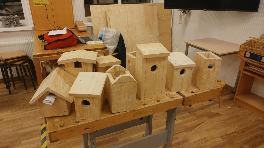
Bygg fågelholkar i träslöjden, och använd dem i undervisningen i fler ämnen!
Fågelholkar i träslöjden
Förutom att det är en bra slöjduppgift så kan man göra något spännande och intressant biologi- och teknikprojekt av det också. Eleverna kan sätta upp fågelholkarna runt skolan och förse dem med olika sensorer och kamera för att övervaka, logga och undersöka om och när det flyttar in fåglar i dem, samt lite annan information som temperatur, luftfuktighet och lufttryck. Man kan t ex använda sig av Micro:bit eller Raspberry Pi med lämpliga sensorer till (t ex envirobit från Pimoroni eller Enviro till Raspberry Pi). Det data som loggas kan även användas i matematikundervisningen för att sammanställa till tabeller, olika typer av diagram och grafer och för att beräkna medelvärden m.m.
Här är en lista på fåglar som häckar i holkar och kan tänkas bygga bo i en observationsholk:
Vanligast: Talgoxe Behöver hål med minst 32 mm diameter. På vintern används holkarna som vindskydd när talgoxarna ska sova.
Nötväcka Behöver ca 30 mm diameter men använder helst holkar med 50 mm hål som den då murar igen till lagom storlek. Bottenytans kant bör vara 15 cm.
Göktyta Behöver 32 mm diameter. Ganska sällsynt. Vill ha mycket djup holk (40 cm mellan hål och botten).
Talltita Behöver 30 mm diameter. Bara i eller nära barrskog. Svår att få att häcka i holk. Den vill hacka ut bohålet själv. Fyll holken med sågspån upp till ingångshålet så kan fåglarna tömma den och sedan bygga sitt bo.
Svartmes Behöver 28 mm diameter. Bara i eller nära barrskog. Vill ha en holk nära marken, helst i knähöjd.
Tofsmes Behöver 28 mm diameter. Bara i eller nära barrskog.
Lappmes Behöver 30 mm diameter. Bara i eller nära barrskog med inslag av björk och endast i nordligaste Sverige.
Tornsvala (tornseglare) Behöver 45 mm diameter. Ganska svår att få att häcka i holk. Häckar i vanliga holkar mest i norra Sverige. Helst ska holken i så fall sättas upp liggande, men specialholkar kan också användas. Viktigast är att holkarna placeras högt så att fåglarna kan låta sig falla en bit för att få luft under vingarna vid utflygningen. Det får inte heller finnas trädgrenar eller andra hinder framför ingångshålen.
Trädkrypare Bara i eller nära skog. Behöver speciell holk av tjärpapp eller trä med smalt springformat ingångshål på sidan. Springan skall vara 25—30 mm bred och 50—100 mm lång.
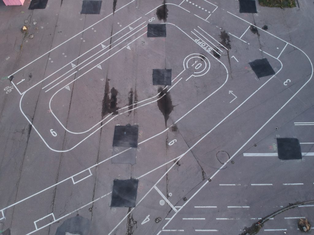
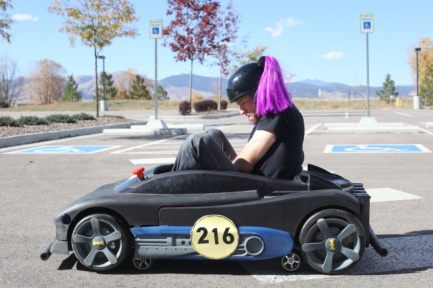
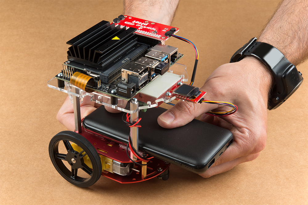
The thrill of taking a corner, extremely low to the ground, with your gut telling you these g-forces are not normal… that’s why we spend countless hours building these silly Power Wheels vehicles. The giggles and grins are unavoidable! These cars are so much fun to drive — and even more fun to race!
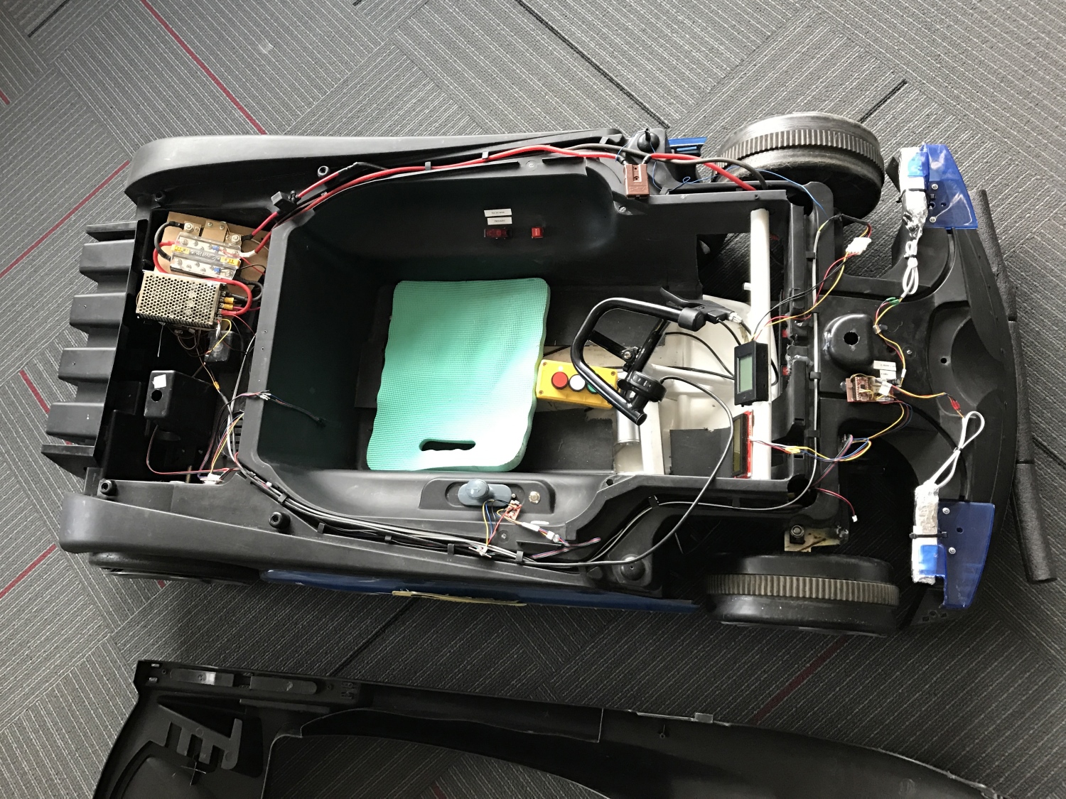
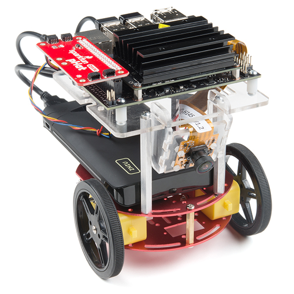
In 2016, SparkFun had its eighth annual Autonomous Vehicle Competition. This year saw the introduction of a new rule: you needed to carry a human (or a 20lb dead weight in the form of a watermelon if you were too chicken). To do this, my wife, Alicia, and I modified a Batmobile Power Wheels and combined it with a Razor chassis. The result was an extremely zippy electric go-kart that left a perma-grin on everyone who drove it.
Our goal was to create a vehicle that could quickly and easily switch between human driver and driverless modes so that we could compete in both PRS and A+PRS categories. In the end, Alicia placed a very respectable third place in the driver category, and I did not finish (DNF) in the autonomous category, running into numerous hay bales.
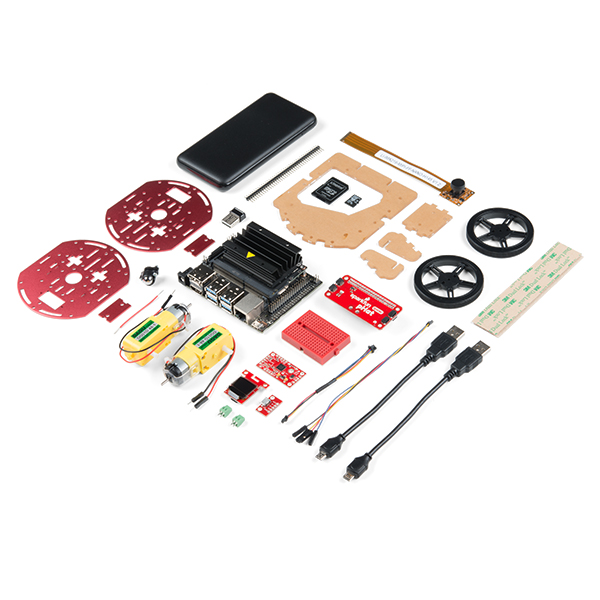
This tutorial attempts to document a six-month build process for an Autonomous + Power Racing Series (A+PRS) vehicle. Every autonomous vehicle is unique, and the requirements of each will vary from build to build.
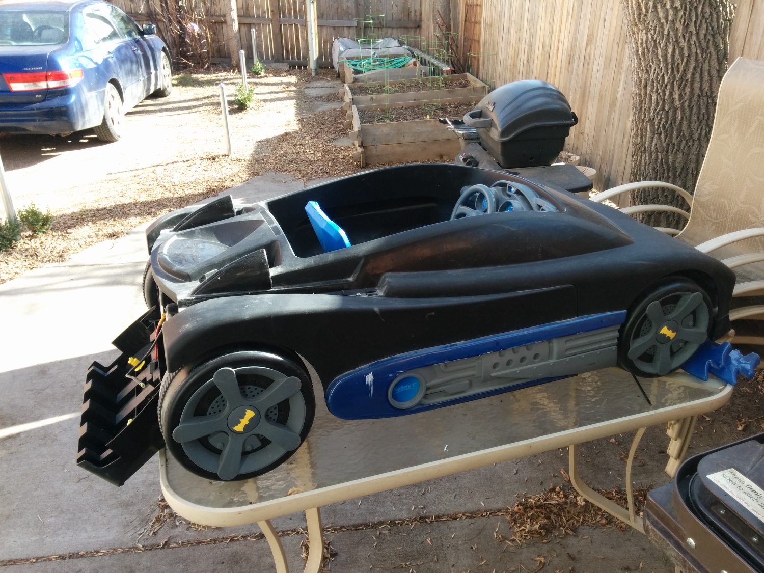
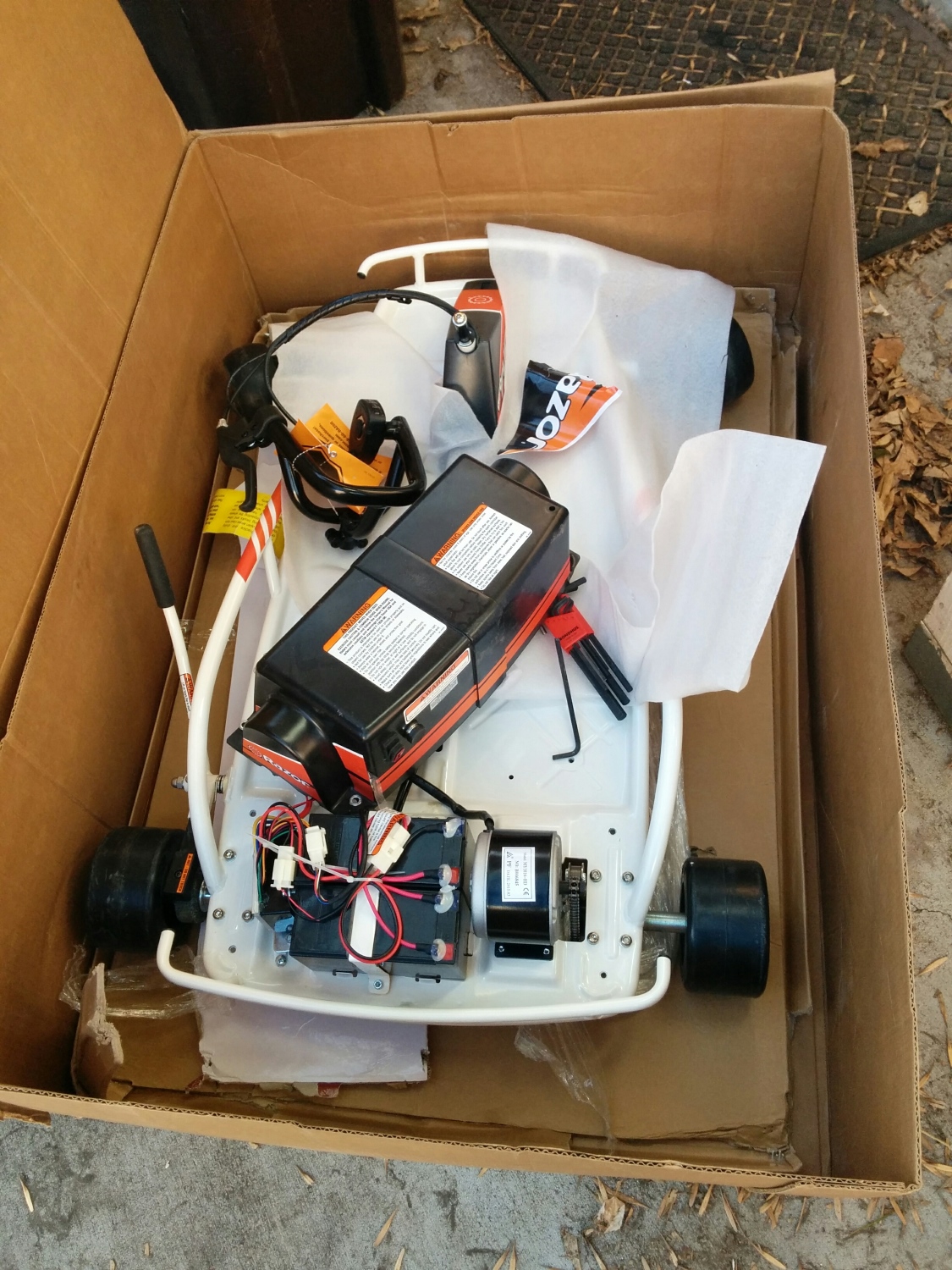
The AVC rules stipulate that you cannot spend more than $500 on your total budget and that you have to stay within certain size restrictions. We started trolling craigslist to see what was out there and immediately found a plethora of free or cheap “broken” Power Wheels. When a Batmobile for $25 popped up, we quickly snagged it.
Dusty with dog hair and dead spiders — it’s perfect!
The primary failure of all used Power Wheels is a dead battery. The Batmobile was no different; as soon as we put in a new 12V SLA (Sealed Lead Acid), it happily, albeit slowly, drove around. There is nothing magical about “Power Wheels” branded batteries; get the right voltage (usually 12V, sometimes 6V), and you can use almost any battery you’d like.
The original batmobile chassis blow molded plastic at its finest. The wheels are hollow, the motor is designed to move a child slowly (and reasonably safely), and the steering is littered with bits of metal but mostly loose and wobbly. While the stock chassis was capable of moving adults weighing in at around 200lbs, we knew it wouldn’t handle racing, so we decided to find a metal chassis to sit underneath.
Note the size of the motor and battery. Those are about to get much larger.
Razor is known for their kick scooters, but they’re in the electric go-kart market as well. We found a Razor Drifter Open Box for $165. The Drifter had the steering, brakes, wheels and chassis sorted out for us! Additionally, the Drifter came with a stock 24V battery, 250W motor and 250W motor controller.
Many PRS and AVC competitors are talented enough to weld their own chassis together. DIY welding is a great way to save money, but it may take weeks of fabrication. Because we planned to enter the autonomous field, we decided to find a ready-made chassis and spend our time building and debugging the autonomous bits.
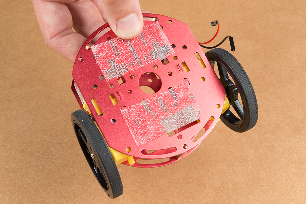
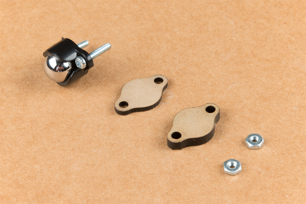
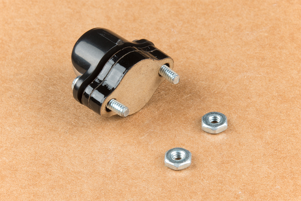
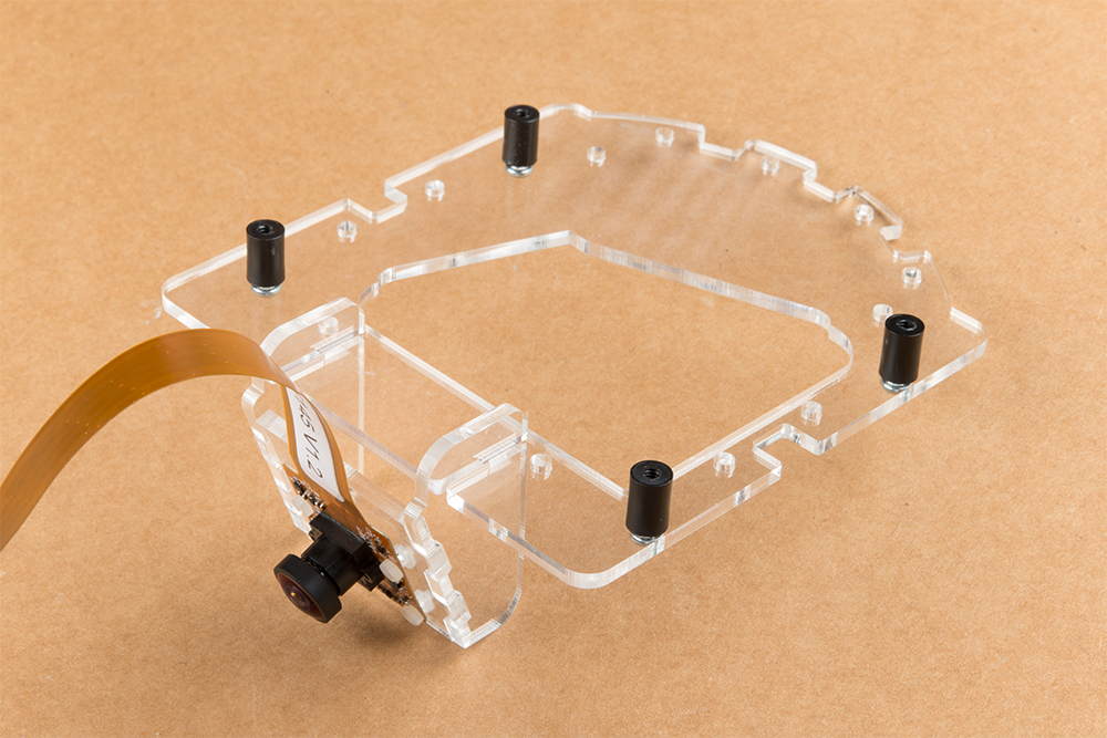
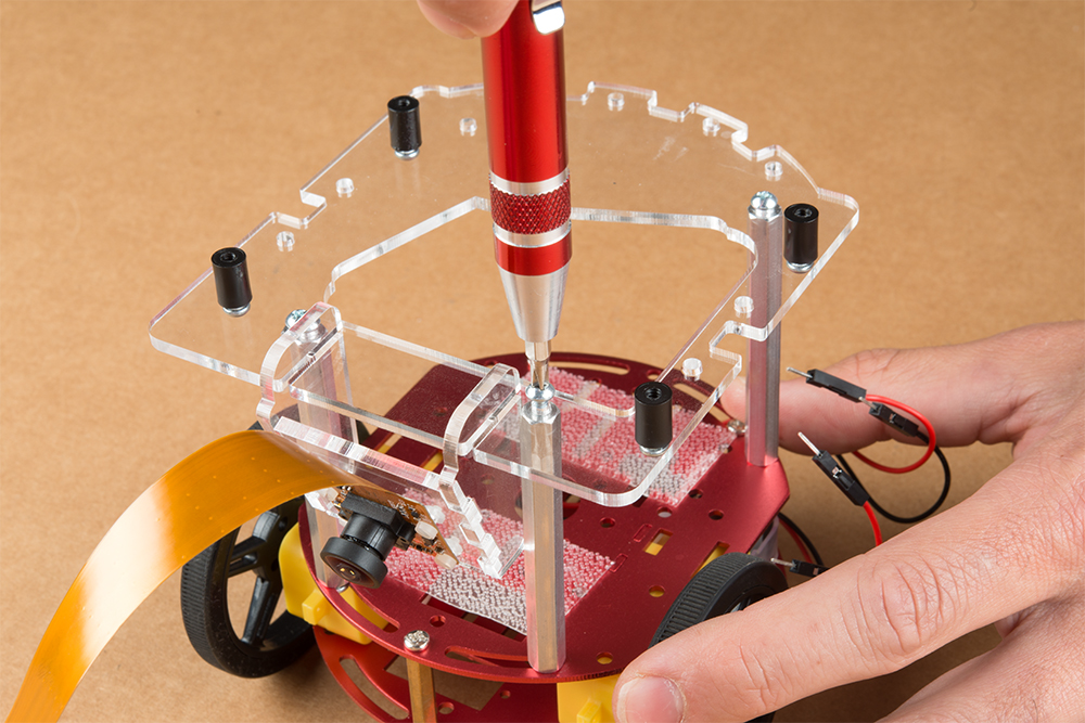
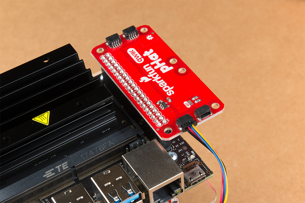
Putting on a Hat
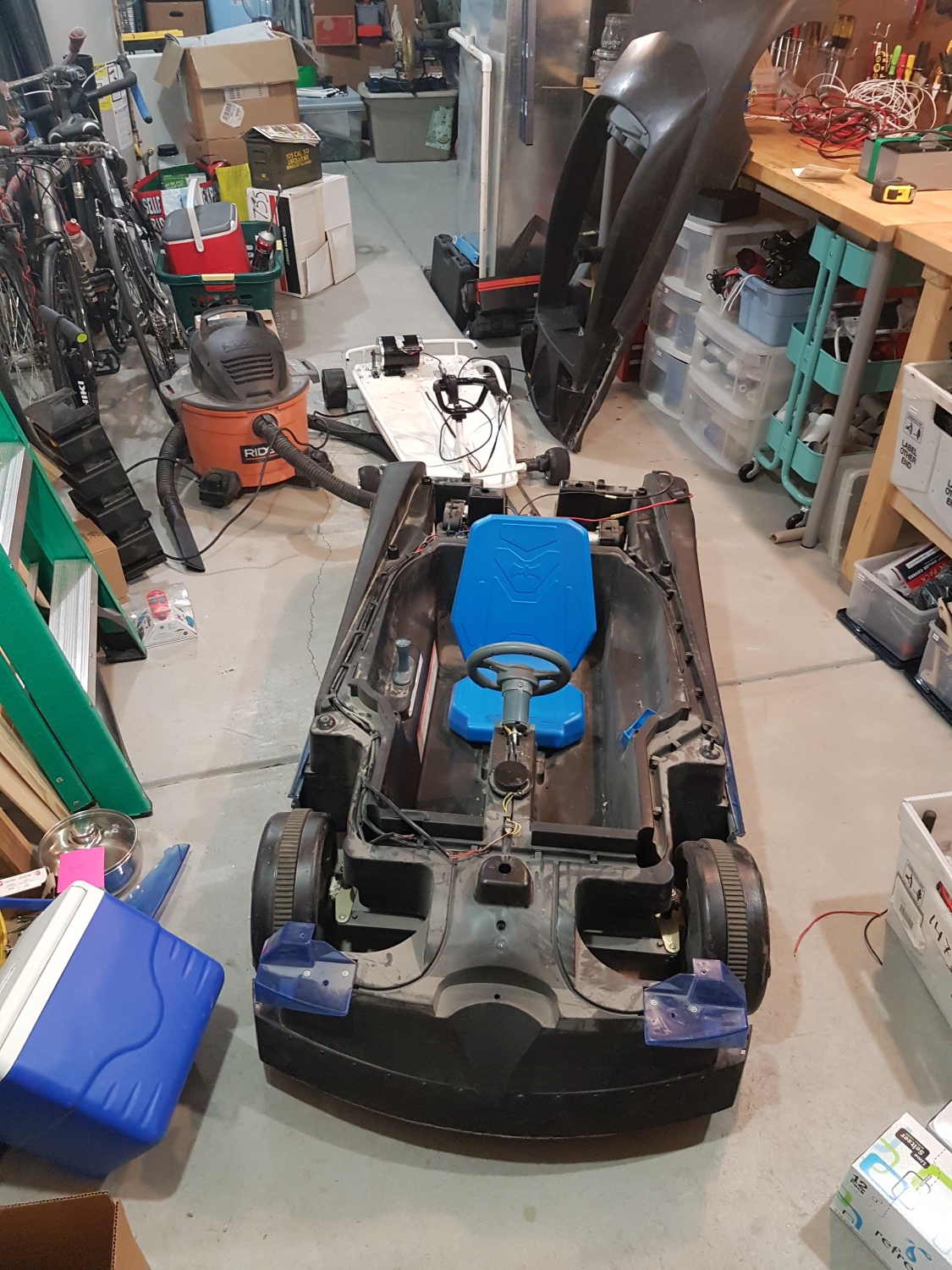
Once we had the Power Wheels and the Razor chassis, we had to combine the two.
We slid the razor chassis underneath the plastic batmobile shell. The razor chassis has strength where we needed it most: steering, chassis, brakes, drive train, everything. The plastic batmobile is just there as a shell. The four solid plastic+rubber razor wheels make contact with the ground. The four hollow batmobile wheels hover above the ground and are there only for cosmetic looks (for the lulz).
A Power Wheels meets a Drifter
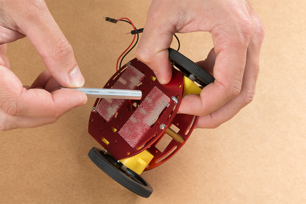
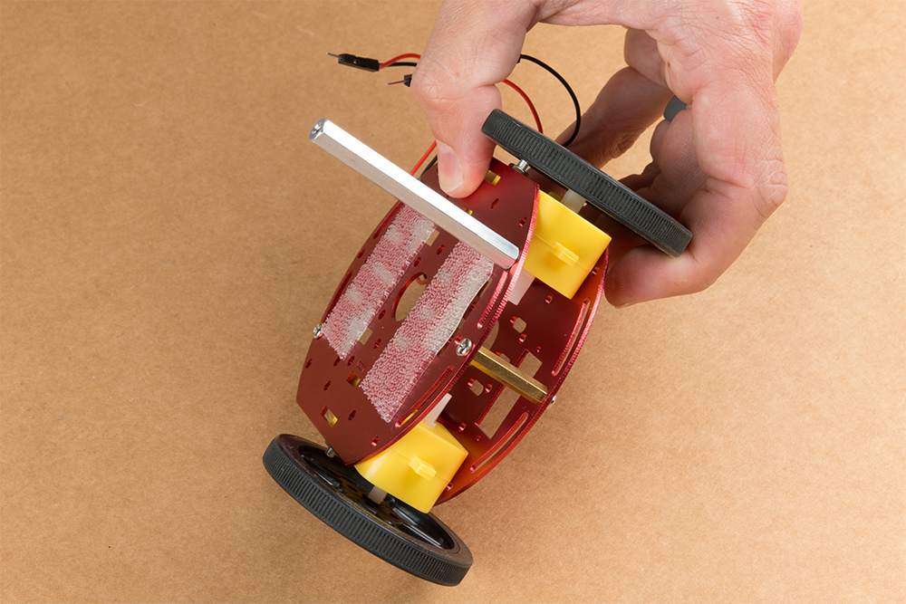
At some point you have to get out the reciprocating saw and severely modify your beautiful Power Wheels. We laid the Batmobile over the Razor and proceeded to chop off all the bits that got in the way.
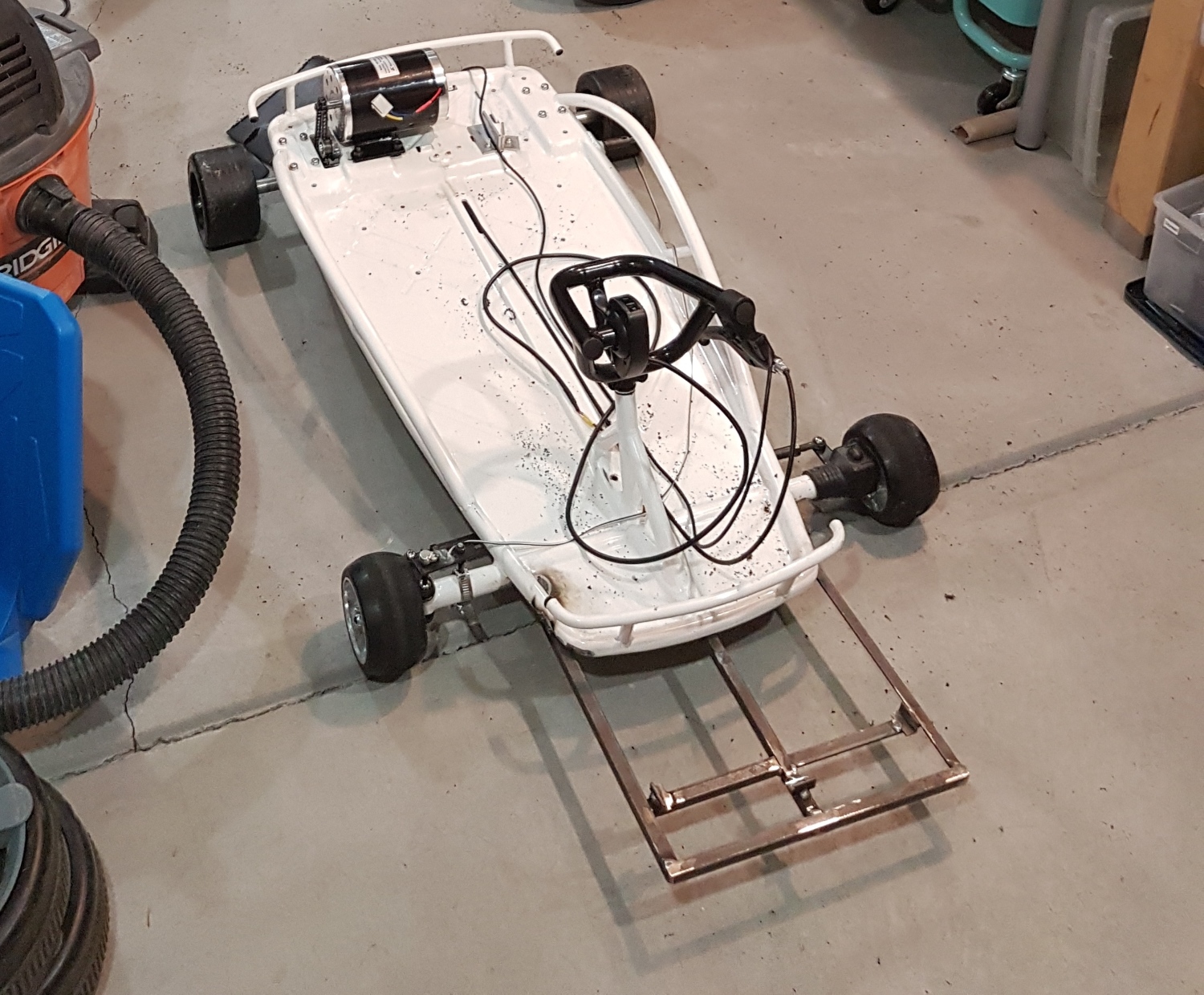
Bare metal chassis before shell is laid on top
Seats? Where we’re going, we don’t need seats!
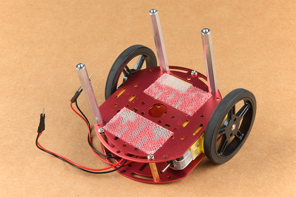
Pleasingly, the Batmobile sits on top of the chassis under its own structural support. We didn’t need to add all-thread or other standoffs. Even though they don’t do anything, we reattached the original wheels just so it looked extra wacky.
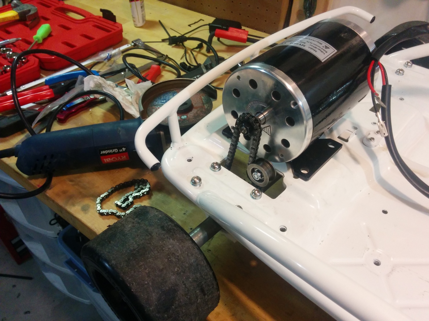
Motor and Motor Control
Moar!
In 2016, A+PRS allowed 48V systems, so the first thing we did was remove the 24V motor and install a 1,000W 48V/21A motor. The PRS rules limit any system to 1,400W, so we could have gone larger had budget constraints not been kicking in fast. New mounting holes were drilled into the chassis, and a different gear had to be mounted to the end of the motor. But it all went well. The stock chassis even included a chain tensioner that proved invaluable!
The MY1020 48V motor we used is common on the PRS circuit and performed great. However, our original 1,000W motor controller (you should already be able to tell what’s coming) did not do so well. Our first tests of the 48V system in an open parking lot worked great until the motor controller overheated and failed. And when MOSFET-based motor controllers fail, they fail unsafe, meaning our vehicle decided to go to 100 percent throttle and stay there. This is why we have safety switches! Alicia and I were able to kill the vehicle before anyone got hurt.
This failure should have been prevented: a motor controller should be rated for at least 2 times what you calculate your maximum load will be. In our case, if we wanted to control a 1kW motor, we should have been using a motor controller rated to a constant 2kW load. Luckily, the A+PRS rules don’t require you to record how much money you spent (and burned up); you have to report only what is on the vehicle as it rolls on race day.
The new, larger 5kW motor controller
We quickly located a larger, 5kW motor controller (this one even had reverse!) and got it on order. This larger motor controller has been working swimmingly ever since. Find a motor controller with reverse. You’ll be tempted to drive your souped-up Power Wheels in weird places (like the SparkFun inventory aisles), and a reverse gear allows for hilarious 5-point turns.
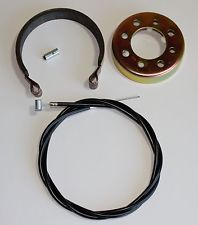
Brakes
Go-kart drum brakes on eBay
The Razor chassis had the classic drum brake, perhaps the weakest link of the Razor. While the stock brake was probably the appropriate size for a 75lb child with stock 24V batteries, our brakes got really squishy once we added an additional 125lbs of meat bag, batteries and plastic bits. We rarely, if ever, used the brakes during races, but the PRS rules stipulate that your qualifying lap must end with the driver crossing the finish line and braking to a stop:
At the end of the hot lap, your car will have to come to a complete stop within 18ft of when its transponder crossed the start/finish line. Deliberately skidding, swerving or spinning out is not an acceptable method of braking for the brake test.
Alicia had to do an impressive combination of hard braking, swerving, skidding and sliding with such a dramatic flair that she wooed the judges into not noticing how dodgy our brakes were. We’ll have disc brakes installed before we roll in the 2017 race.
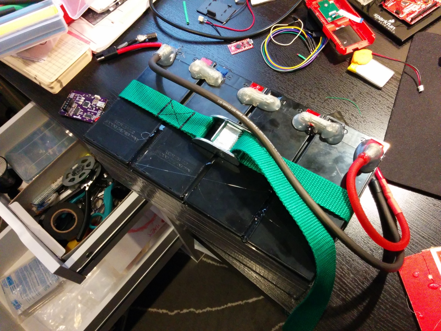
Batteries
Battery holder welded onto the front of the chassis
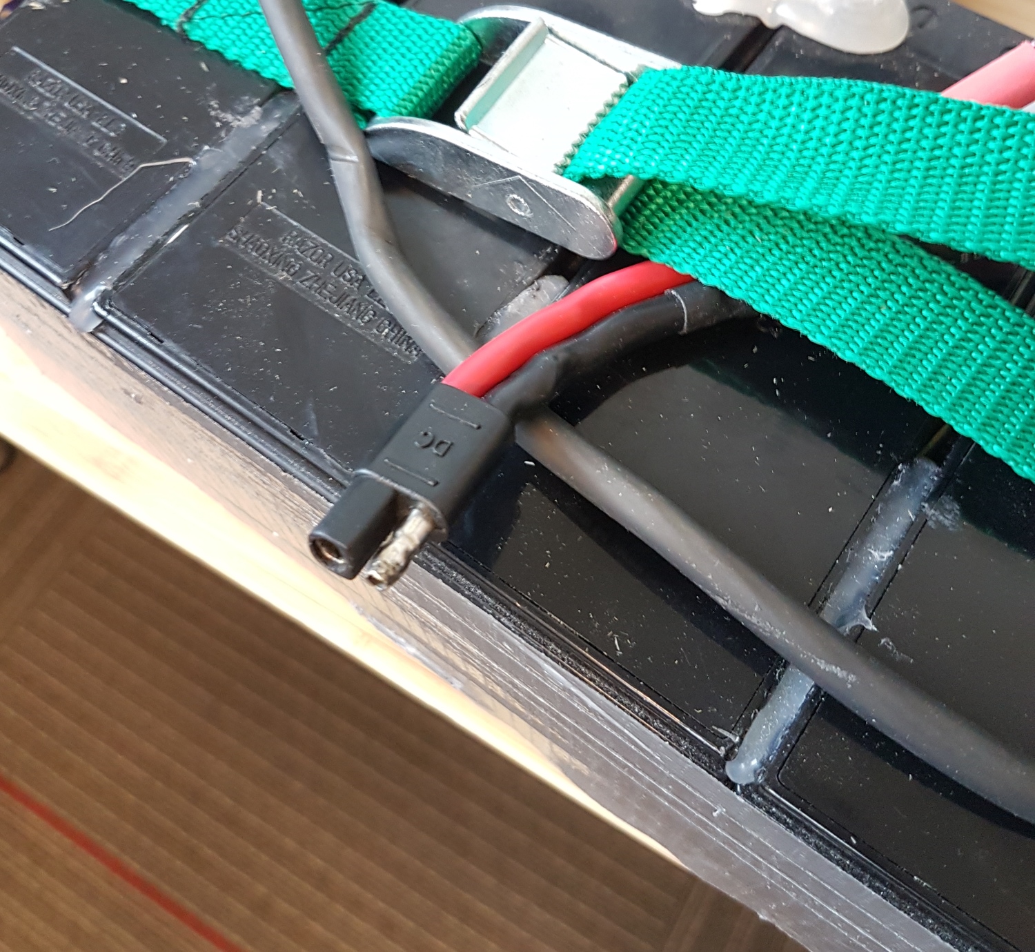
As part of the motor upgrade, we needed to increase the battery voltage to 48V. To save money, we reused the super common batteries that came with the 24V Razor chassis. Razor was smart; they looked at the SLA (Sealed Lead Acid) battery industry and picked the most common size. This just happened to be the same battery that goes into nearly every UPS on the planet. We purchased two additional UPS-size batteries (way cheaper than buying Razor-brand batteries) and wired them in series.
Four batteries combined in series
Taping the cells together and adding a bead of hot glue between the cells made the pack nicely rigid. A low-cost, polarized, high-current connector finished off the pack. We had an old strap lying around that made all the difference in the world; it’s a lot more comfortable carrying the pack one-handed by its handle than with two hands underneath.
Avoid fires and other bad things. Use polarized connectors for your batteries.
Wire
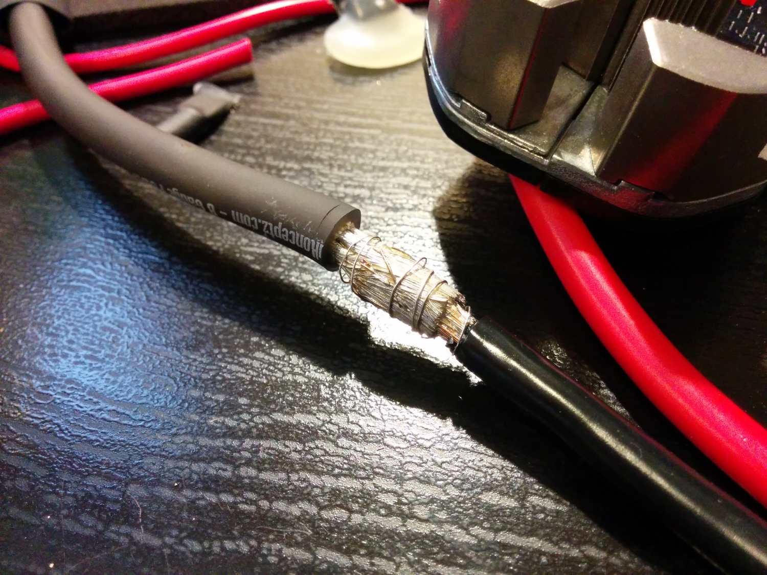
Soldering large-gauge wire
We originally spec’d out some really nice, super flexible silicone-sheathed 8AWG wire for power distribution. I don’t think we would do this again; 10AWG would have been fine, and probably even 12AWG. As 8-gauge is far less common, the wire and connectors are more expensive, and the larger gauge wire takes a lot more soldering heat — it’s just a pain to work with. If you need the current capacity, go for it, but for our extremely zippy, 48V 20A vehicle, 8-gauge wire was overkill.
If you decide to use super flexible, large gauge wire, spend some time on the internet reading about how to solder this type of wire.
The best technique I found:
Make sure you’ve got heat shrink in place
Turn your soldering iron up to 425C (way hotter than the 325C usually needed)
Push the ends of wire together
Wrap tightly with 30AWG wire wrap wire
Liberally apply flux
Heat and insert lots of solder until the joint turns silver
Here’s a good video demonstrating this technique:
Kill Switch
We documented how to build a wireless kill switch while making margaritas. It was a ton of fun, so we’ll skip the bits of the wireless kill switch system here.
Zroooommmm!
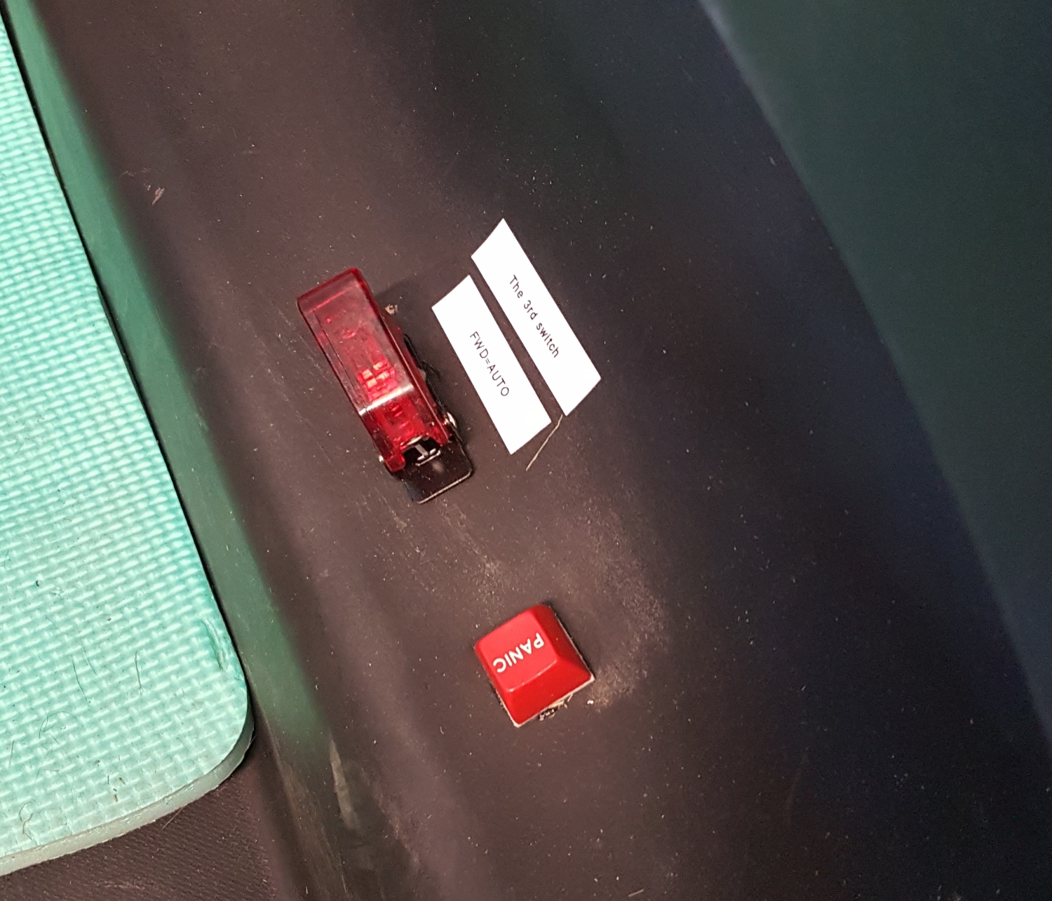
In addition to the wireless disconnect, we had a large, red mushroom kill switch that disconnected the battery with a pleasing and authoritative ”thunk.” Pulling up on the mushroom button reconnects the battery to the system.
Batman logo or Bitman logo?
As a pleasant bonus feature, the mushroom kill switch got rid of the nasty sparks. When connecting the battery to the motor controller, there was such an inrush of current into the capacitors and electronics that the connector would spark. Once we got the kill switch installed, we could connect/disconnect batteries without these sparks.
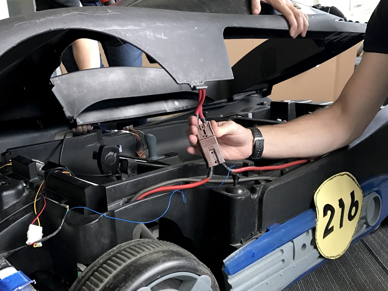
Connector between kill switch and power bus
The top of the Batmobile was easily removed, but because it had the kill switch installed we needed a way to disconnect it easily from the power bus. We found a great high-power connector in a dead server UPS. These are often called ”winch connectors”, because they are higher current. With this connector, we are able to quickly disconnect the kill switch and remove the top when we need to get at the inside of the vehicle.
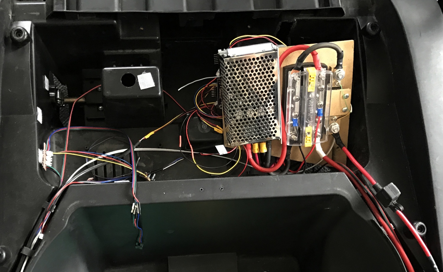
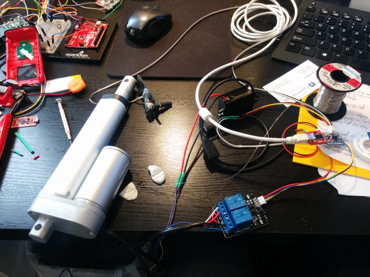
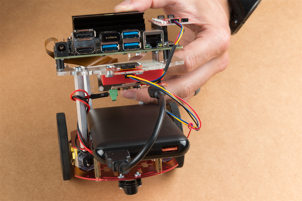
Control Electronics
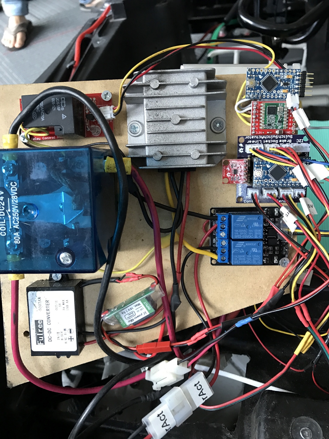
Power converters, motor kill relays, steering relays, locomotion controller and wireless communication
The control electronics are complex. We had a total of seven microcontrollers on this beast, plus three used in the distance sensors for a total of 216 bits of processing power. The system operated on an I2C bus with the brain sending commands to the locomotion controller and LCD and receiving data from the sensors.
The wiring underneath the Batmobile cover
For a previous 2010 AVC entry, I did everything on a single microcontroller. This made coding and debugging a challenge. On our 2016 entry, we focused each sub-system to do one thing very well.
The subsystems are broken down as follows:
Brain Controller: A SAMD21 Mini was used to communicate with and process all the data from the distance sensors, GPS and compass, and to send out commands to control throttle and steering. It monitored a start switch and relayed debug information to an LCD.
Locomotion Controller: An Arduino Pro Mini read the throttle, steering position, brake switch and autonomous rocket switch. It controlled motor speed and the linear actuator for steering.
Wireless Kill Switch: An Arduino Pro Mini lived in the wireless kill switch, a requirement for the autonomous part of our Batmobile. To learn more about the wireless controller, check out our tutorial on how to build a wireless kill switch.
A dedicated Arduino Pro Mini controlled the relays for the wireless kill switch system.
Debug LCD: We counted our LCD screen as a microcontroller since it has an Arduino in it.
Sensor Combinator: A SAMD21 Mini polled the serial GPS and I2C compass.
Laser Controller: A SAMD21 Mini controlled the three serial-based laser distance sensors, combined the relevant information and responded to requests from the Brain.
Three STM32s were the brains within the laser distance sensors.
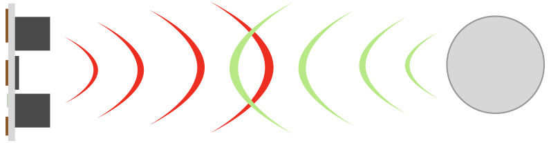
Interested in learning more about distance sensing?
Learn all about the different technologies distance sensors use and which products would work best for you next project.TAKE ME THERE!
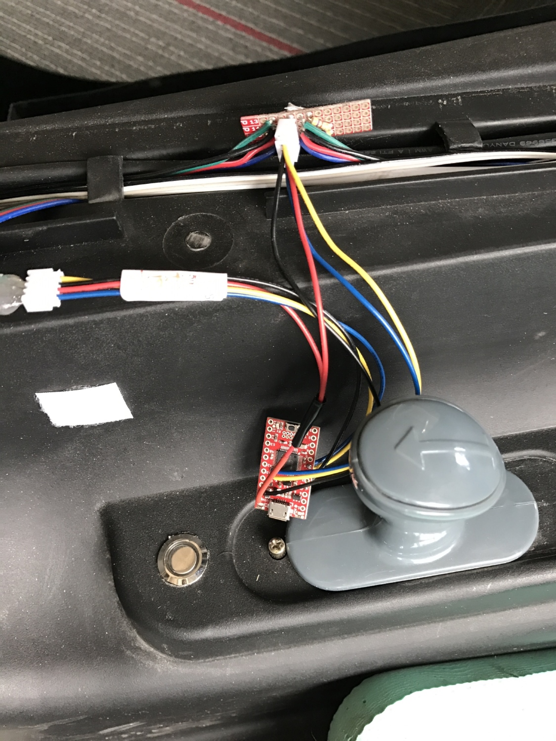
Control Electronics – Brain
The Brain is a SAMD21 Mini. It sends commands over the I2C bus to the locomotion controller and debug LCD.
4-pin JST connector at the top of the image: We used a 4-wire bus (5V, GND, SDA, SCL) for communication and had various taps throughout the bus to allow devices to be attached. This worked really well and allowed for devices to be moved around when needed.
4-pin JST connector to the left: This was four wires to the button. To tell the vehicle to begin navigating under autonomous control, we used a metal momentary push button that illuminates when everything is online and happy. The human presses the button twice, and the car commences racing.
Big gray handle: This was the original forward and reverse knob that we reused to control the direction switch on the motor controller (two pins when shorted together caused one direction, when open caused the other direction).
The massive and poorly written control code for the Brain can be found here.
EEPROM for Waypoints
The SAMD21 does not have internal EEPROM. Because we needed to store GPS waypoints and other configuration data to non-volatile memory, we used an external I2C EEPROM. Yes, you can use something called emulated EEPROM on the SAMD21, but, every time you reprogram the board, you will overwrite anything previously stored in emulated EEPROM. The external EEPROM made it much easier to store and recall waypoints and settings without having to mash together in the main control code.
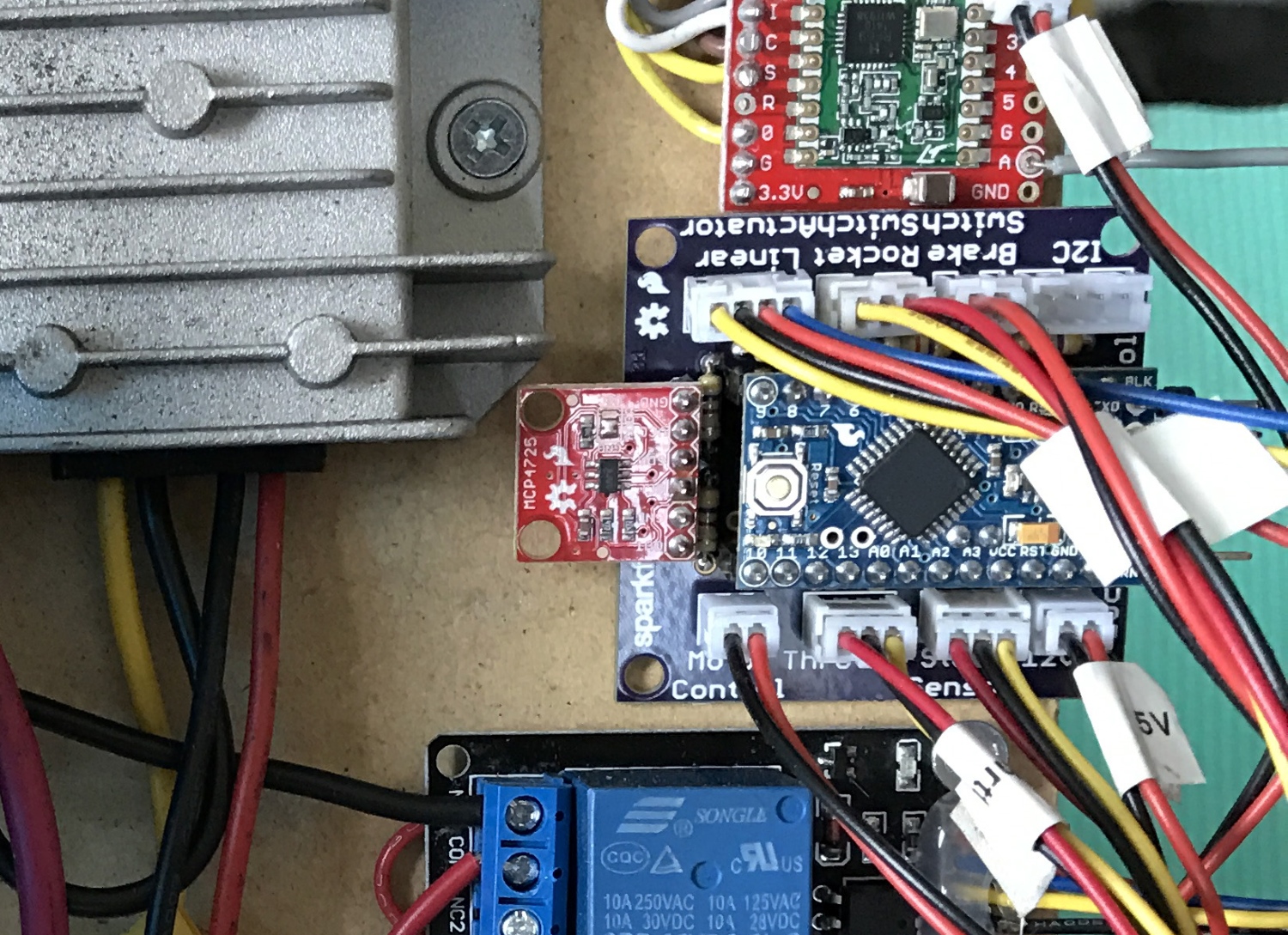
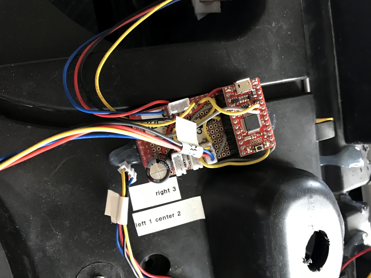
Control Electronics – Locomotion
Locomotion Controller hooked up
Note the polarized connectors and prodigious labeling! You DO NOT want to be guessing what gets plugged into where at 11 p.m. before race day. The Locomotion Controller code is available here, and the PCB layout here.
Because we eventually wanted this beast to be autonomous, we needed to put a controller in the middle between the throttle and the motor controller. We used an Arduino Pro Mini that did a huge variety of sensing and control:
Read the throttle
Output analog voltage to the motor controller
Read the brake switch
Read the steering position
Controlled the linear steering actuator
Read the human/robot control switch
Received and responded to control commands over I2C
Don’t panic
The controller would monitor the rocket switch and brake switch. If a human ever pressed the brakes or turned off the rocket switch, the controller would go into safety shutdown and ignore any commands from the brain.
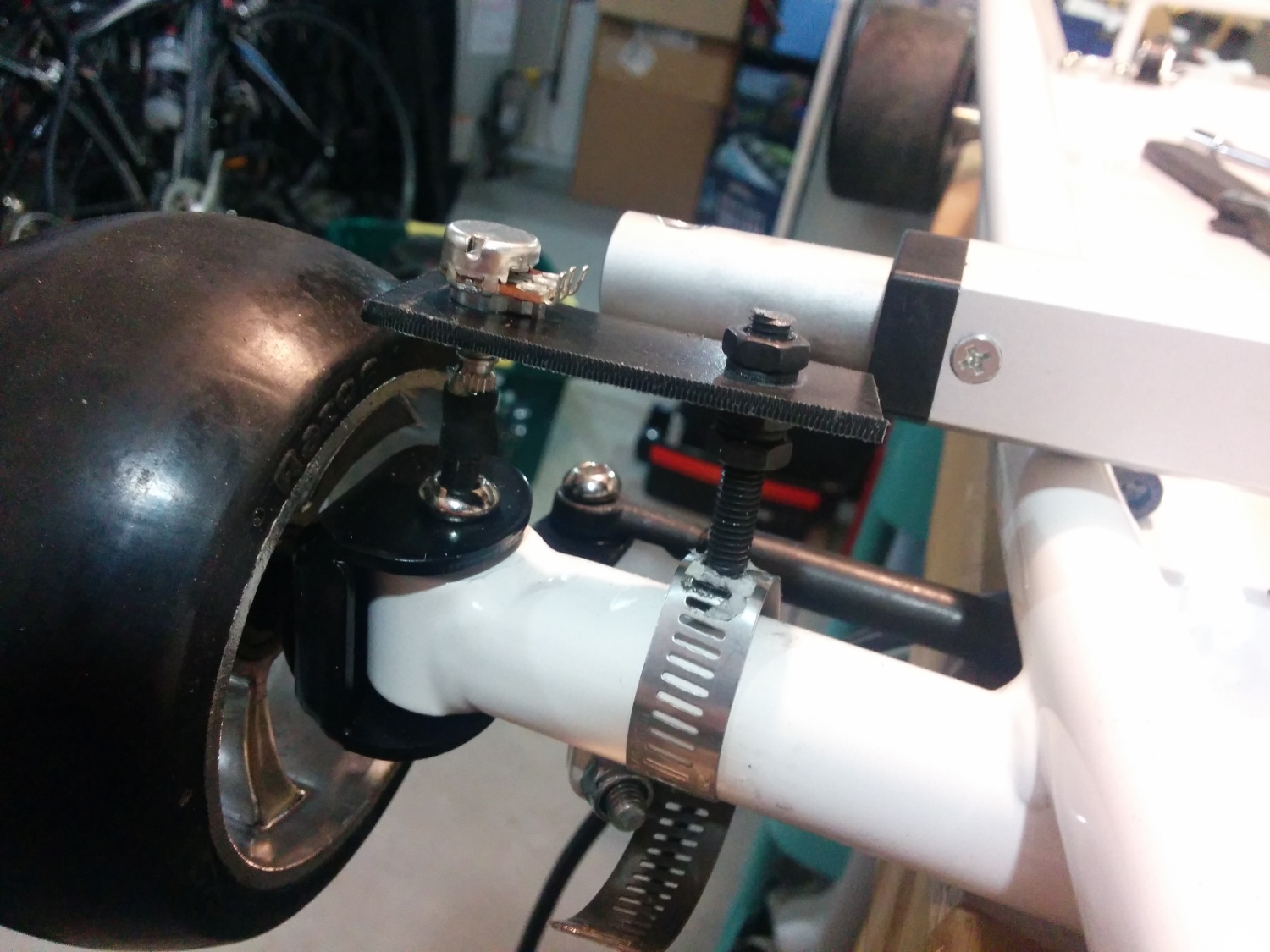
Steering was controlled using a 12V linear actuator over-voltaged to 24V for extra speed. Two relays controlled the forward/backward motion.
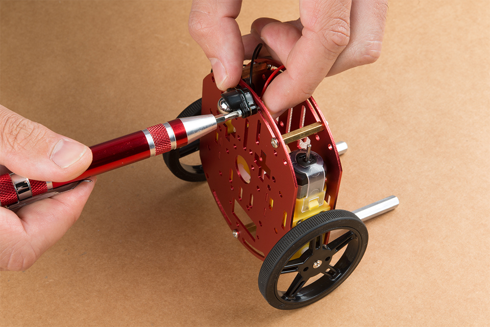
Steering position was obtained by cutting a hex wrench to about 1” and inserting that wrench into the bolt that rotates with the wheel. The wrench was then connected to a 10k trimpot using adhesive-lined heat shrink — this trick is known as the ”poor man’s coupler:” a 3-wire ribbon connected the trimpot back to the locomotion controller. It worked well, but we had to keep the analog signal wire away from the power bus; otherwise, bad noise got into the ADC readings.
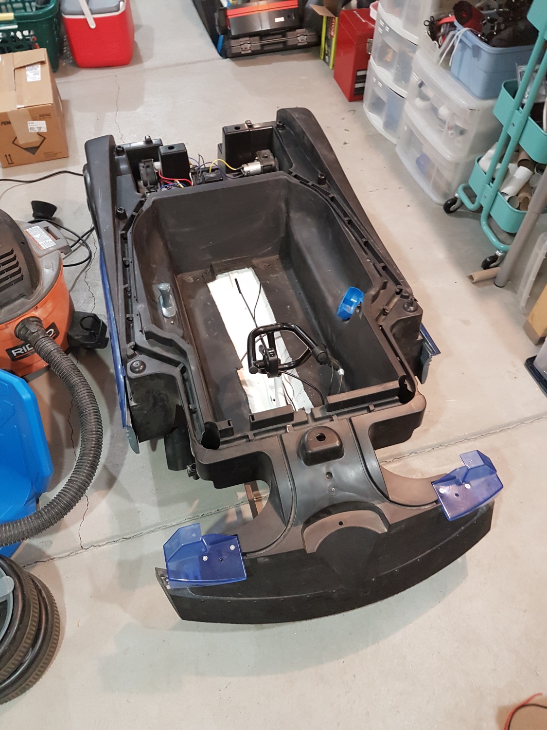
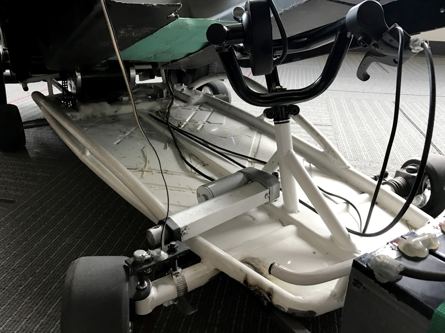
Chassis with the Batmobile raised to see the steering actuator
For future vehicles, we’re going to change this setup. It worked well enough, but once the bolt connected the actuator to the steering, you couldn’t drive the car; only the computer could. So rather than driving the car to the start line, we had to carry this 75lb beast. So painful. In the future, we plan to find a back-drivable actuator or maybe drive-by-wire.
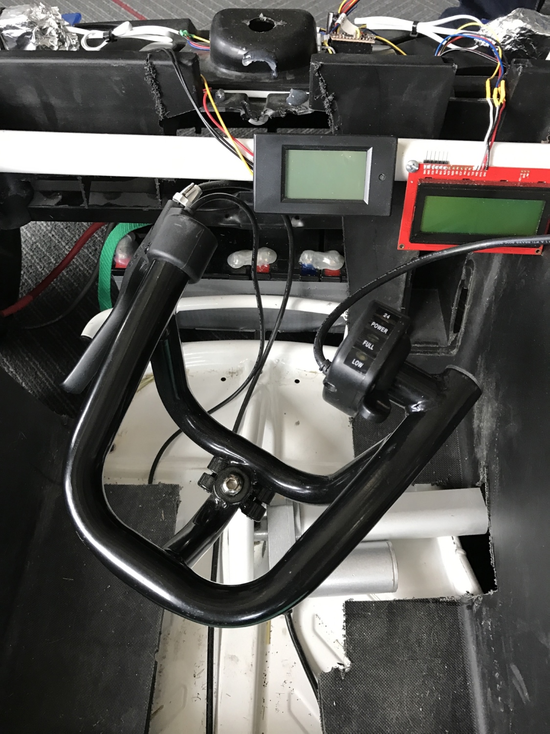
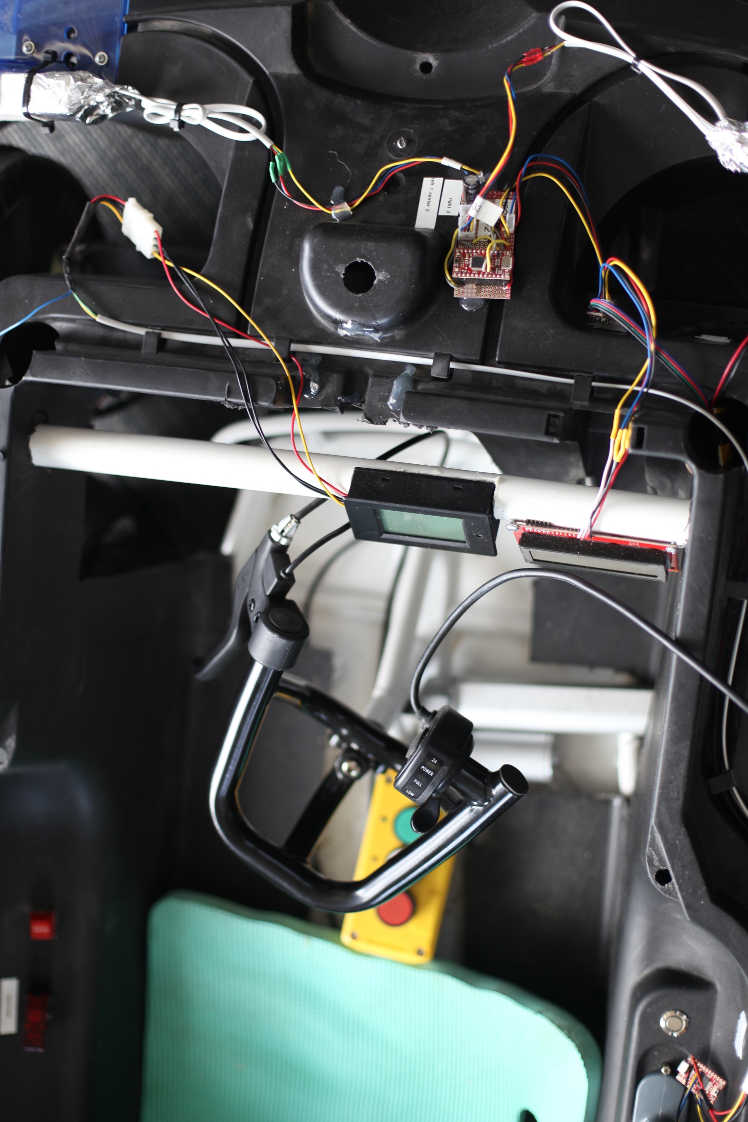
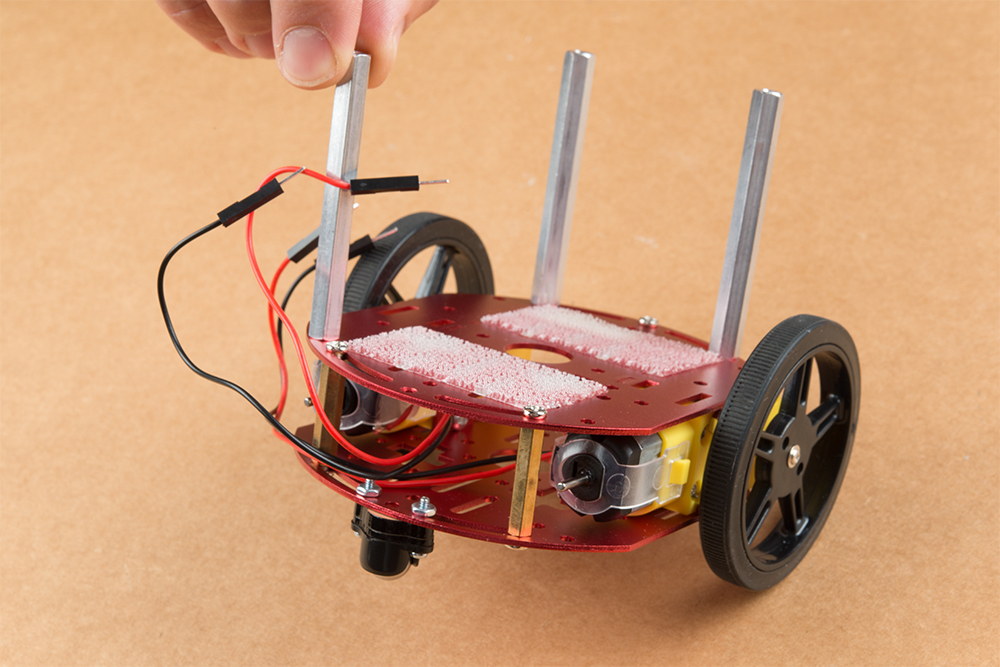
Control Electronics – Displays
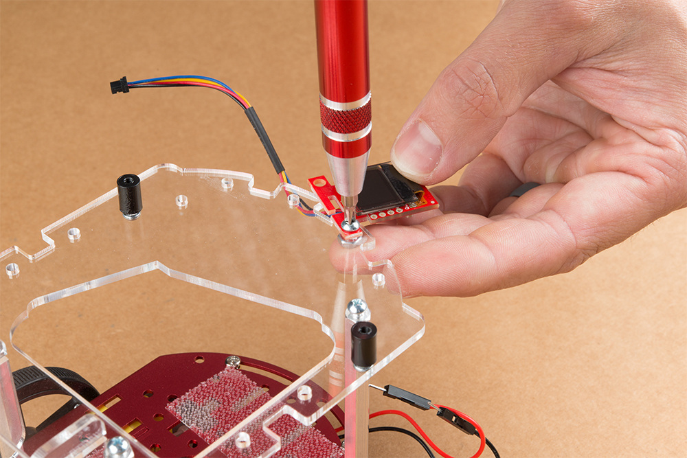
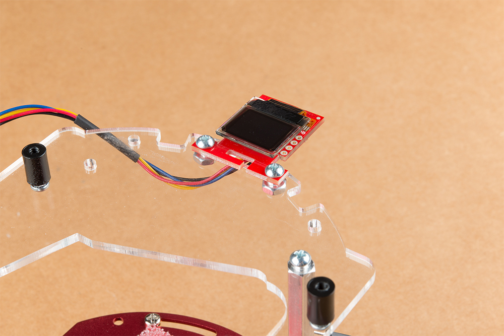
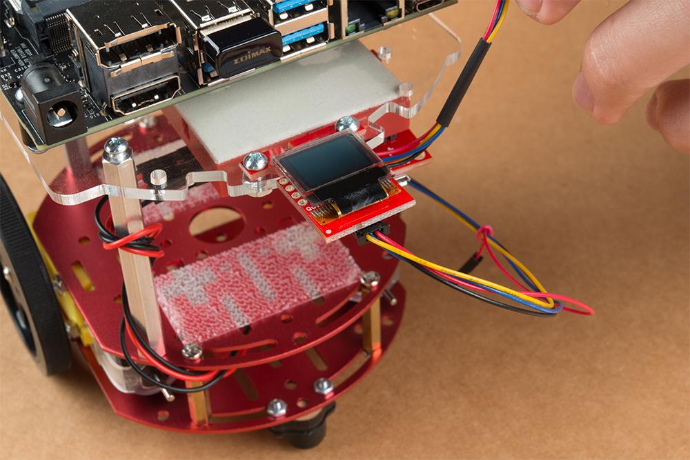
Throttle and displays
We cut notches in a 1” tube of PVC and mounted two displays in the Batmobile. The center display is the power meter. Nearly every A+PRS and PRS competitor used these super low-cost power meters to show the battery voltage. We had some issues with it, but it worked well enough. In the end, we noticed the drop in vehicle speed (indicating battery drain) long before we noticed the display was indicating a lower pack voltage. But, it did help us make decisions about when to pit (never!) because the nominal 48V pack voltage was dropping down to 42V where we could begin to damage the SLA.
The display on the right is the 20×4 character debug LCD. It’s basically a souped-up version of our 20×4 SerLCD display (it’s a prototype product, coming soon to a theater near you!).
Control Electronics – Sensors
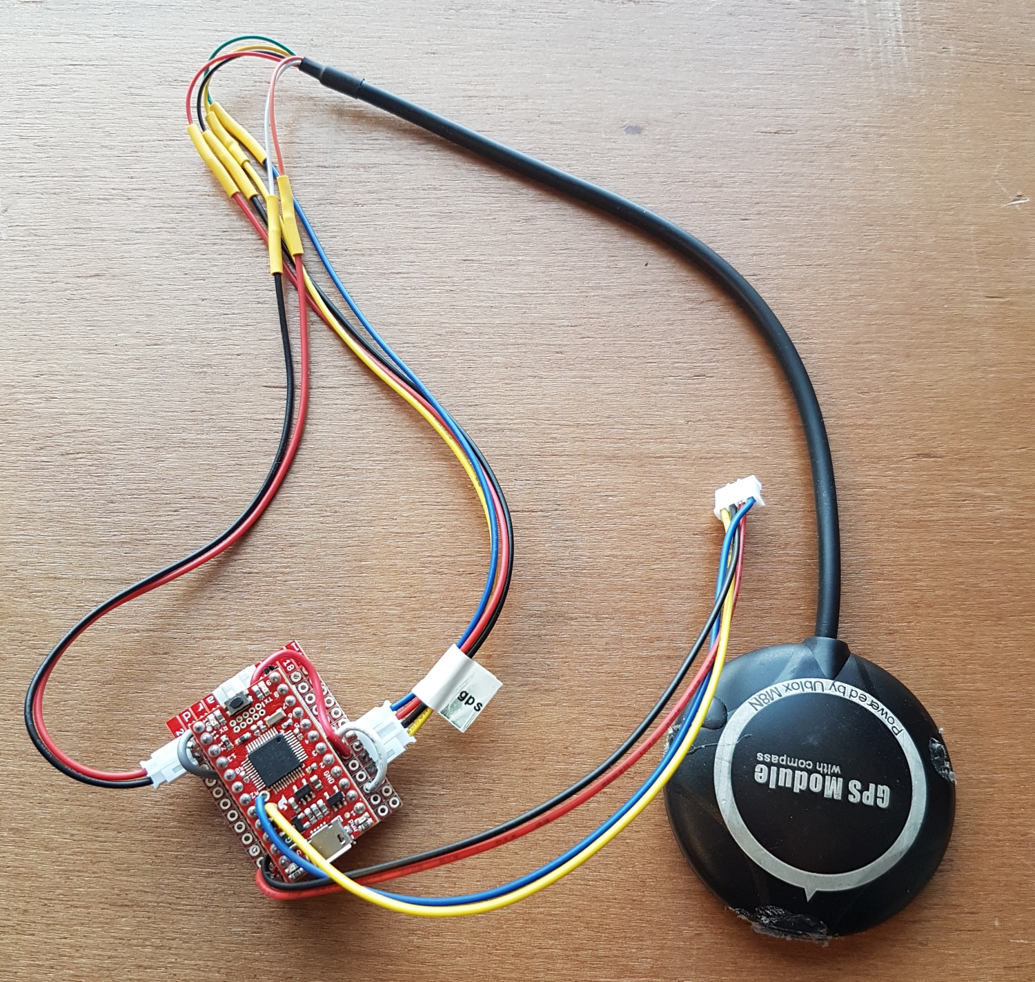
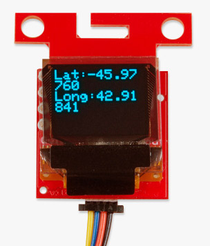
GPS+Compass connected to SAMD21
The Sensor Combinator is a SAMD21 Mini that monitors a GPS receiver and an I2C compass. We decided to use a SAMD21 because it can be configured to have multiple hardware serial and I2C ports. This is needed if you want to isolate I2C devices from the main bus. We wanted the Brain to ask for the heading and get the heading; the Sensor Combinator took care of the low-level I2C function of the compass and heading calculations. Similarly, the Combinator listened to the serial stream from the u-blox based GPS module and parsed out all the needed Latitude/Longitude/SIV information.
The code for the Sensor Combinator can be found here.
Control Electronics – Lasers
Laser tape measures seen on the front of the car, wrapped in foil
We hacked three laser tape measures in order to get distance to any objection front, left or right of the car. Laser tape measures are getting cheaper, and while the read rate (3Hz at the best of times) is not great for LIDAR, it’s fast enough for basic, low-cost autonomy.
Laser Controller at front of car
Unfortunately, the laser tape measures threw off enough RF to interfere with our GPS module, so we wrapped the lasers in foil. These sensors deserve their own tutorial, which will be written soon.
Laser Controller with labels
Again we chose the SAMD21 Mini to help us control and combine the serial information coming from the three sensors. The Laser Controller would send the pertinent control strings to the tape measures and monitor the responses, combining them into distances for left/right/center. The Brain would request these values from the Laser Controller over I2C.
Note the prodigious amounts of labels and polarized connectors (JSTs work great!). This system required lots of debugging but worked well because we were able to quickly disconnect and reconnect various aspects of the system.
The code for the Laser Controller can be found here.
Problems
As with any project, we had a large number of problems and hurdles to overcome along the way. Here are a few that really hurt.
** EMI and GPS **
The Laser tape measures caused significant interference with GPS reception. We eventually moved the GPS module to the rear of the car, which improved positional accuracy. However, the motor caused interference with the compass.
** DC Motor EMF **
DC motors produce a ton of electromagnetic noise. We originally had the 48V battery powering the entire car. However, when the motor would kick on, it would cause enough ripple to make the Brain glitch and reset. We tried powering the I2C bus separately, but, because the Locomotion Controller needed to be attached to the motor controller, a GND connection had to be shared. The noise eventually found its way over the I2C bus. In the future we will optically isolate the I2C bus.
** Lack of EEPROM **
Because the SAMD21 doesn’t have internal EEPROM, we were unable to store GPS waypoints on the board. We fixed this by using an I2C-based EEPROM.
** Switching Steering Between Driver/Driverless **
It was difficult to attach and detach the linear actuator from the rack and pinion steering. Once the actuator was attached to the steering, a driver could not actively steer (for example, to the starting line). This could be fixed with a different actuator that could be back-driven, or we could go full monty and detach the steering column from the steering and have it control a trimpot that, in turn, controls the linear actuator (drive by wire).
Tips / Best Practices
Tip 1) Start early — These vehicles take a large amount of time. Get together with friends and start hacking. It’s a great labor of love, and drifting in a 15mph go-kart will make you giggle.
Tip 2) Get reverse — Get a motor controller with reverse. It will make it so you can drive your car where you want it instead of carrying your car where you need it.
Tip 3) Use connectors! — I’ve written about using connectors a few times. Use polarized connectors and a label maker to make it clear what plugs in where.
Tip 4) Size your motor and motor controller correctly — We blew our motor controller because it was underrated. A friend of ours smoked his motor because he was pushing too much current. Pick your system voltage and current, and then double the ratings wherever you can.
Tip 5) Beware of interference — These vehicles can pull 30 amps or more when accelerating, which can cause large electromagnetic fields. Keep unshielded cables and sensitive sensors away from power wires.
Tip 6) Wireless control and sensor logging — After you pick up your 75lb vehicle and drag it to the start line for the fifth time, you’ll understand the need for remote control. Create a wireless system that allows you to take over control of the vehicle from afar so you can drive it where you need it. And transmit the sensor data so you can see what the vehicle is doing.
Detta är en artikel från SparkFun, December 17, 2012
Introduction
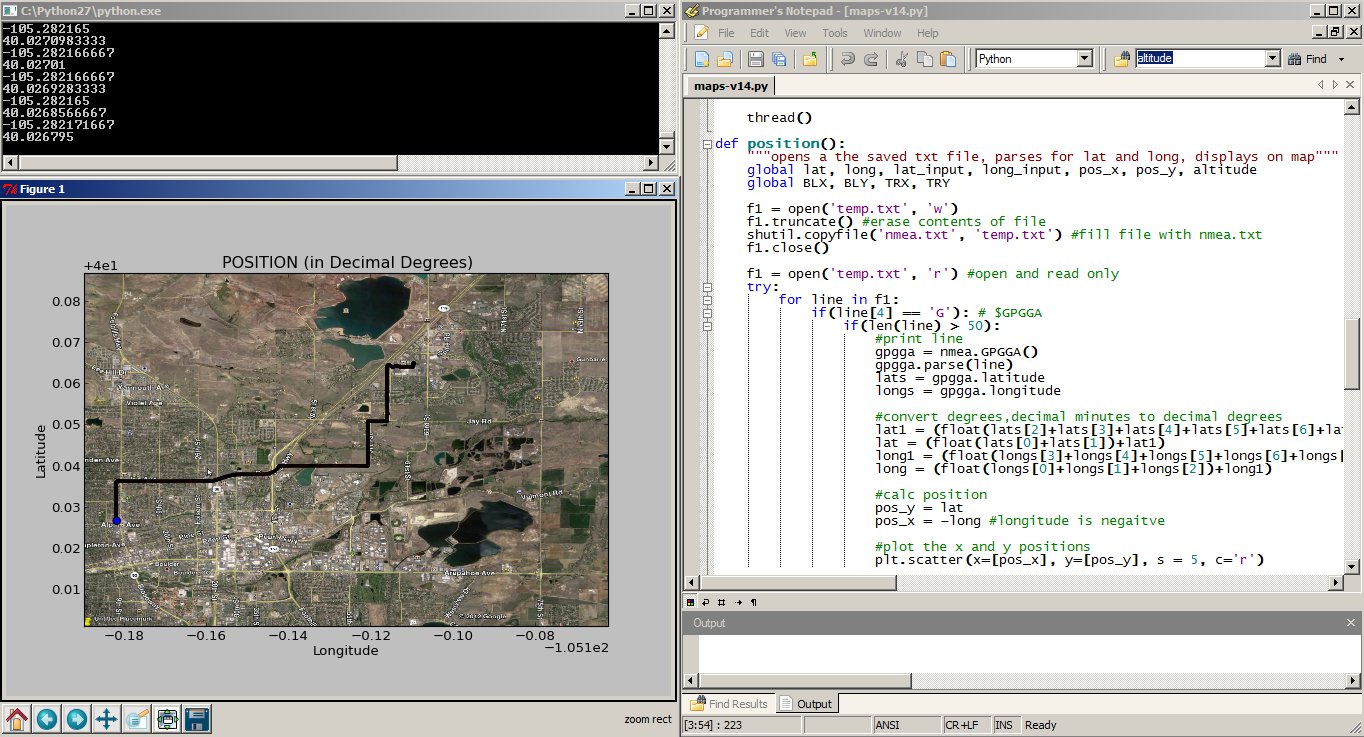
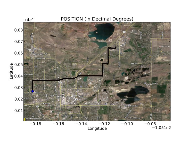
In my quest to design a radio tracking system for my next HAB, I found it very easy to create applications on my computer and interact with embedded hardware over a serial port using the Python programming language. My goal was to have my HAB transmit GPS data (as well as other sensor data) over RF, to a base station, and graphically display position and altitude on a map. My base station is a radio receiver connected to my laptop over a serial to USB connection. However, in this tutorial, instead of using radios, we will use a GPS tethered to your computer over USB, as a proof of concept.
Of course, with an internet connection, I could easily load my waypoints into many different online tools to view my position on a map, but I didn’t want to rely on internet coverage. I wanted the position of the balloon plotted on my own map, so that I could actively track, without the need for internet or paper maps. The program can also be used as a general purpose NMEA parser, that will plot positions on a map of your choice. Just enter your NMEA data into a text file and the program will do the rest.
Showing a trip from SparkFun to Boulder, CO.
This tutorial will start with a general introduction to Python and Python programming. Once you can run a simple Python script, we move to an example that shows you how to perform a serial loop back test, by creating a stripped down serial terminal program. The loopback test demonstrates how to send and receive serial data through Python, which is the first step to interacting with all kinds of embedded hardware over the serial port. We will finish with a real-world example that takes GPS data over the serial port and plots position overlaid on a scaled map of your choice. If you want to follow along with everything in this tutorial, there are a few pieces of hardware you will need.
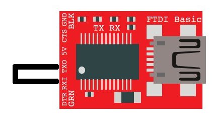
For the loopback test, all you need is the FTDI Basic. For the GPS tracking example, you will need a GPS unit, as well as the FTDI.
What is Python?
If you are already familiar with installing and running Python, feel free to skip ahead. Python is an interpreted programming language, which is slightly different than something like Arduino or programming in C. The program you write isn’t compiled as a whole, into machine code, rather each line of the program is sequentially fed into something called a Python interpreter. Once you get the Python interpreter installed, you can write scripts using any text editor. Your program is run by simply calling your Python script and, line by line, your code is fed into the interpreter. If your code has a mistake, the interpreter will stop at that line and give you an error code, along with the line number of the error.
The holy grail for Python 2.7 reference can be found here:
At the time of this tutorial, Python 2.7 is the most widely used version of Python and has the most compatible libraries (aka modules). Python 3 is available, but I suggest sticking with 2.7, if you want the greatest compatibility.
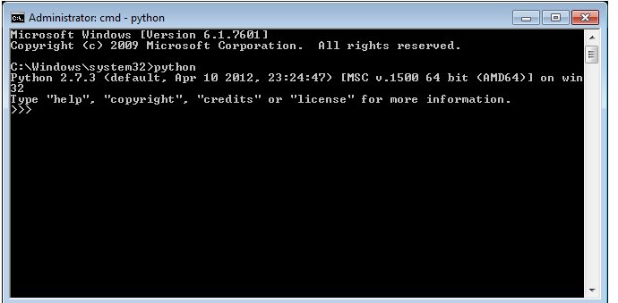
After you install Python, you should be able to open a command prompt within any directory and type ’python’. You should see the interpreter fire up.
If you don’t see this, it is time to start some detective work. Copy your error code, enter it into your search engine along with the name ’python’ and your OS name, and then you should see a wealth of solutions to issues similar, if not exact, to yours. Very likely, if the command ’python’ is not found, you will need to edit your PATH variables. More information on this can be found here. FYI, be VERY careful editing PATH variables. If you don’t do it correctly, you can really mess up your computer, so follow the instructions exactly. You have been warned.
If you don’t want to edit PATH variables, you can always run Python.exe directly out of your Python installation folder.
Running a Python Script
Once you can invoke the Python interpreter, you can now run a simple test script. Now is a good time to choose a text editor, preferably one that knows you are writing Python code. In Windows, I suggest Programmers Notepad, and in Mac/Linux I use gedit. One of the main rules you need to follow when writing Python code is that code chunks are not enclosed by brackets {}, like they are in C programming. Instead, Python uses tabs to separate code blocks, specifically 4 space tabs. If you don’t use 4 space tabs or don’t use an editor that tabs correctly, you could get errant formatting, the interpreter will throw errors, and you will no doubt have a bad time.
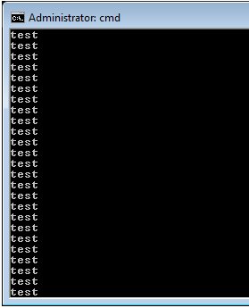
For example, here is a simple script that will print ’test’ continuously.
# simple script
def test():
    print "test"
while 1:
    test()
Now save this code in a text editor with the extention your_script_name.py.
The first line is a comment (text that isn’t executed) and can be created by using a # .
The second line is a function definition named test().
The third line is spaced 4 times and is the function body, which just prints ”test” to the command window.
The third line is where the code starts in a while loop, running the test() function.
To run this script, copy and paste the code into a file and save it with the extention .py. Now open a command line in the directory of your script and type:
python your_script_name.py
The window should see the word ’test’ screaming by.
To stop the program, hit Ctrl+c or close the window.
Installing a Python Module
At some point in your development, you will want to use a library or module that someone else has written. There is a simple process of installing Python modules. The first one we want to install is pyserial.
Download the tar.gz file and un-compress it to an accessible location. Open a command prompt in the location of the pyserial directory and send the command (use sudo if using linux):
python setup.py install
You should see a bunch of action in the command window and hopefully no errors. All this process is doing is moving some files into your main Python installation location, so that when you call the module in your script, Python knows where to find it. You can actually delete the module folder and tar.gz file when you are done, since the relevant source code was just copied to a location in your main Python directory. More information on how this works can be found here:
FYI, many Python modules can be found in Windows .exe installation packages that allow you to forgo the above steps for a ’one-click’ installation. A good resource for Windows binary files for 32-bit and 64-bit OS can be found here:
This example requires using an FTDI Basic or any other serial COM port device.
Simply, connect the TX pin to the RX pin with a wire to form a loopback. Anything that gets sent out of the serial port transmit pin gets bounced back to the receive pin. This test proves your serial device works and that you can send and receive data.
Now, plug your FTDI Basic into your computer and find your COM port number. We can see a list of available ports by typing this:
python -m serial.tools.list_ports
If you are using linux:
dmesg | grep tty
Note your COM port number.
Now download the piece of code below and open it in a text editor (make sure everything is tabbed in 4 space intervals!!):
import serial

#####Global Variables######################################
#be sure to declare the variable as 'global var' in the fxn
ser = 0

#####FUNCTIONS#############################################
#initialize serial connection
def init_serial():
    COMNUM = 9 #set you COM port # here
    global ser #must be declared in each fxn used
    ser = serial.Serial()
    ser.baudrate = 9600
    ser.port = COMNUM - 1 #starts at 0, so subtract 1
    #ser.port = '/dev/ttyUSB0' #uncomment for linux

    #you must specify a timeout (in seconds) so that the
    # serial port doesn't hang
    ser.timeout = 1
    ser.open() #open the serial port

    # print port open or closed
    if ser.isOpen():
        print 'Open: ' + ser.portstr
#####SETUP################################################
#this is a good spot to run your initializations
init_serial()

#####MAIN LOOP############################################
while 1:
    #prints what is sent in on the serial port
    temp = raw_input('Type what you want to send, hit enter:\n\r')
    ser.write(temp) #write to the serial port
    bytes = ser.readline() #reads in bytes followed by a newline
    print 'You sent: ' + bytes #print to the console
    break #jump out of loop
#hit ctr-c to close python window
First thing you need to do before running this code is to change the COM port number to the one that is attached to your FTDI. The COMNUM variable in the first few lines is where you enter your COM port number. If you are running linux, read the comments above for ser.port.
Now, if you want to send data over the serial port, use:
ser.write(your_data)
your_data can be one byte or multiple bytes.
If you want to receive data over the serial port, use:
your_data = ser.readline()
The readline() function will read in a series of bytes terminated with a new line character (i.e. typing something then hitting enter on your keyboard). This works great with GPS, because each GPS NMEA sentence is terminated with a newline. For more information on how to use pyserial, look here.
You might realize that there are three communication channels being used:
ser.write – writes or transmitts data out of the serial port
ser.read – reads or receives data from the serial port
print – prints to the console window
Just be aware that ’print’ does not mean print out to the serial port, it prints to the console window.
Notice, we don’t define the type of variables (i.e. int i = 0). This is because Python treats all variables like strings, which makes parsing text/data very easy. If you need to make calculations, you will need to type cast your variables as floats. An example of this is in the GPS tracking section below.
Now try to run the script by typing (remember you need to be working out of the directory of the pythonGPS.py file):
python pythonGPS.py
This script will open a port and display the port number, then wait for you to enter a string followed by the enter key. If the loopback was successful, you should see what you sent and the program should end with a Python prompt >>>.
To close the window after successfully running, hit Ctrl + c.
Congratulations! You have just made yourself a very simple serial terminal program that can transmit and receive data!
Read a GPS and plot position with Python
Now that we know how to run a python script and open a serial port, there are many things you can do to create computer applications that communicate with embedded hardware. In this example, I am going to show you a program that reads GPS data over a serial port, saves the data to a txt file; then the data is read from the txt file, parsed, and plotted on a map.
There are a few steps that need to be followed in order for this program to work.Install the modules in the order below.
Install modules
Use the same module installation process as above or find an executable package.
The above process worked for me on my W7 machine, but I had to do some extra steps to get it to work on Ubuntu. Same might be said about Macs. With Ubuntu, you will need to completely clean your system of numpy, then build the source for numpy and matplotlib separately, so that you don’t mess up all of the dependencies. Here is the process I used for Ubuntu.
Once you have all of these modules installed without errors, you can download my project from github and run the program with a pre-loaded map and GPS NMEA data to see how it works:
Or you can proceed and create your own map and GPS NMEA data.
Select a map
Any map image will work, all you need to know are the bottom left and top right coordinates of the image. The map I used was a screen shot from Google Earth. I set placemarks at each corner and noted the latitude and longitude of each corner. Be sure to use decimal degrees coordinates.
Then I cropped the image around the two points using gimp. The more accurate you crop the image the more accurate your tracking will be. Save the image as ’map.png’ and keep it to the side for now.
Hardware Setup
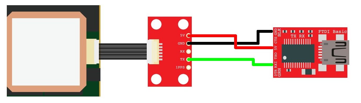
The hardware for this example includes a FTDI Basic and any NMEA capable GPS unit.
EM-406 GPS connected to a FTDI Basic
For the connections, all you need to do is power the GPS with the FTDI basic (3.3V or 5V and GND), then connect the TX pin of the GPS to the RX pin on the FTDI Basic.
It is probably best to allow the GPS to get a lock by leaving it powered for a few minutes before running the program. If the GPS doesn’t have a lock when you run the program, the maps will not be generated and you will see the raw NMEA data streaming in the console window. If you don’t have a GPS connected and you try to run the program, you will get out-of-bound errors from the parsing. You can verify your GPS is working correctly by opening a serial terminal program.
Save the python script into a folder and drop your map.png file along side maps.py. Here is what your program directory should look like if you have a GPS connected:
The nmea.txt file will automatically be created if you have your GPS connected. If you don’t have a GPS connected and you already have NMEA sentences to be displayed, create a file called ’nmea.txt’ and drop the data into the file.
Now open maps.py, we will need to edit some variables, so that your map image will scale correctly.
Edit these variables specific to the top right and bottom left corners of your map. Don’t forget to use decimal degree units!
#adjust these values based on your location and map, lat and long are in decimal degrees
TRX = -105.1621     #top right longitude
TRY = 40.0868       #top right latitude
BLX = -105.2898     #bottom left longitude
BLY = 40.0010       #bottom left latitude
Run the program by typing:
python gpsmap.py
The program starts by getting some information from the user.
You will select to either run the program with a GPS device connected or you can load your own GPS NMEA sentences into a file called nmea.txt. Since you have your GPS connected, you will select your COM port and be presented with two mapping options: a position map…
…or an altitude map.
Once you open the serial port to your GPS, the nmea.txt file will automatically be created and raw GPS NMEA data, specifically GPGGA sentences, will be logged in a private thread. When you make a map selection, the nmea.txt file is copied into a file called temp.txt, which is parsed for latitude and longitude (or altitude). The temp.txt file is created to parse the data so that we don’t corrupt or happen to change the main nmea.txt log file.
The maps are generated in their own windows with options to save, zoom, and hover your mouse over points to get fine grain x,y coordinates.
Also, the maps don’t refresh automatically, so as your GPS logs data, you will need to close the map window and run the map generation commands to get new data. If you close the entire Python program, the logging to nmea.txt halts.
This program isn’t finished by any means. I found myself constantly wanting to add features and fix bugs. I binged on Python for a weekend, simply because there are so many modules to work with: GUI tools, interfacing to the web, etc. It is seriously addicting. If you have any modifications or suggestions, please feel free to leave them in the comments below. Thanks for reading!
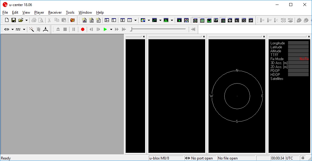
U-center from u-blox is a free software tool for configuring u-blox GPS receivers under Windows. U-center is a dense program with many interface elements. It can be overwhelming at first but over time it will become easier to use. For all its GUI weaknesses, it is very powerful for configuring the u-blox line of modules (such as the NEO-M8P-2 and SAM-M8Q to name a few). In this tutorial, we will be exploring some of its features with the NEO-M8P-2.
Required Software
The software can be obtained from u-blox. To follow along with this tutorial please download and install u-center. Once completed, open it.DOWNLOAD U-CENTER
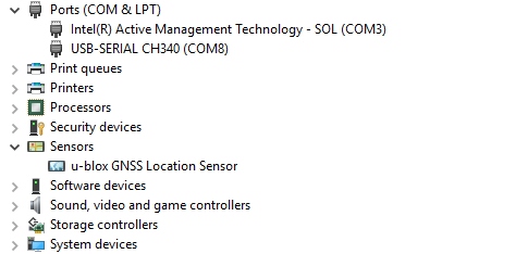
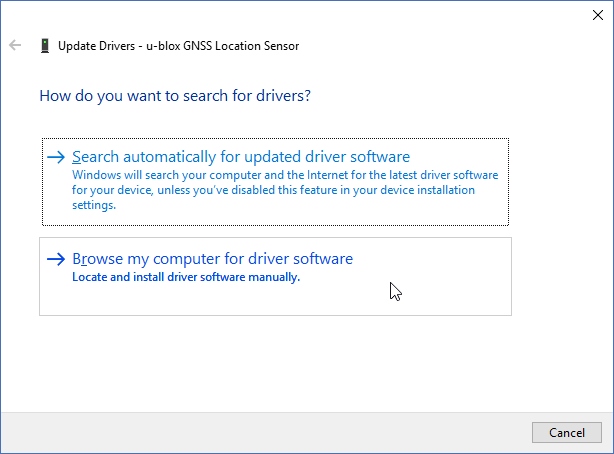
Install Drivers
For this tutorial we’ll assume you have the SparkFun GPS-RTK but u-center can be used with any u-blox based product. Start by attaching a micro-B cable to the GPS-RTK board.
Now open Windows Device Manager. The NEO-M8 series has an annoying feature where the module comes up as a Windows Sensor rather than a serial device. If your u-blox receiver does not appear under COM ports then right click on the u-blox GNSS Location Sensor and then Update Driver. Next, click on Browse my computer for driver software.
Then “Let me pick”…
Select the first USB serial device.
The SparkFun GPS-RTK board should now enumerate as a USB serial COM port. In the list below, the GPS-RTK board is COM12.
Return to u-center and drop down the port list. Select the COM port that is your RTK board. Congrats! You can now use u-center.
Configuring and Outputting NMEA Sentences
Let’s go over a few features you’ll likely use:
Text Console
The text console button will show you the raw NMEA sentences. This is handy for quickly inspecting the visible ASCII coming from the module over USB.
Configure
The configuration button opens the most powerful window. From this window you can inspect and configure new settings. It’s not obvious but when you click on a setting such as ‘MSG (Messages),’ u-center will poll the module for its current state. The ‘10s’ in the corner indicates how old the displayed information is. In this case it’s been 10 seconds since this setting was last queried. Click on the ‘Poll’ button to update the information. Go ahead and select the F0-00 NMEA GxGGA message. As you click the dropdown menu, the software will poll the current settings. It’s a bit disorienting at first but gets better over time.
The MSG configuration is very powerful. It allows you to enable or disable various NMEA sentences as well as binary protocols such as NAV-PVT (checkout the [full protocol datasheet](link text). Once a sentence is selected, such as GxGGA, the check boxes will be populated. If you want to disable the GxGGA sentence for the SPI interface, uncheck the SPI checkbox and then click ‘Send’. Congrats! The GxGGA sentence is no longer presented on the SPI interface. This raises an important fact:
Note: The NEO-M8 series has 4 interfaces: USB(serial), I2C, SPI, and UART. All interfaces can access information simultaneously. This means you can inspect configuration settings over the USB serial port while your Arduino makes setting changes over the I2C port. You can read NMEA sentences over the I2C port or send RTCM data into the module over SPI. It’s all highly configurable.
What is the USB Port on the NEO-M8P?
It’s like any other USB to serial device. It will enumerate on your computer as a COM port and acts as such. It is independent and separate from the UART port that is a dedicated TTL serial port.
If something is not accessible through u-center, it probably means that feature or setting is not compatible with the currently attached device. For example, the UART2 box is grayed out in the image above. The NEO-M8P does not have a second UART so you can’t address it.
Ports
The Ports (PRT) sub-menu under Configuration is very helpful. You can do things like change the baud rate, I2C address, and protocols. Depending on your application, you may want to enable or disable entire interface protocols. For example, if you want to enable NMEA sentences for the SPI interface, you would do it here. Fortunately, the factory default for the NEO-M8P is good for I2C and UART1 for RTK purposes (input of RTCM3 is enabled for both ports).
This is also the menu that allows you to change the I2C address of your GPS-RTK. Because we are big fans of the Qwiic system, we’ll be using the GPS-RTK on the I2C bus. If we had another device on the bus that uses address 0x42 this menu will allow us to change the address of the GPS-RTK.
Poke around the various config menus. If you get your module into an unknown state you can unplug and replug to reset the settings.
Messages
The messages window will allow you to view the various sentences reported by the module. It’s not obvious but if you double click on ‘NMEA’, the tree of messages will fold away. Similarly, if you double click on ‘UBX’, it will expand showing the various UBX sentences. By default, many of these are not enabled.
Resources and Going Further
Ready to get hands-on with GPS?
We’ve got a page just for you! We’ll walk you through the basics of how GPS works, the hardware needed, and project tutorials to get you started.
Once you’ve mastered U-Center you’re ready to begin configuring your Ublox module! Check out some of these related tutorials:Building an Autonomous Vehicle: The BatmobileDocumenting a six-month project to race autonomous Power Wheels at the SparkFun Autonomous Vehicle Competition (AVC) in 2016.GPS-RTK Hookup GuideFind out where you are! Use this easy hook-up guide to get up and running with the SparkFun high precision GPS-RTK board.GPS-RTK2 Hookup GuideGet precision down to the diameter of a dime with the new ZED-F9P from Ublox.
SparkFun’s version of the JetBot merges the industry leading machine learning capabilities of the NVIDIA Jetson Nano with the vast SparkFun ecosystem of sensors and accessories. Packaged as a ready to assemble robotics platform, the SparkFun JetBot Kit requires no additional components or 3D printing to get started – just assemble the robot, boot up the Jetson Nano, connect to WiFi and start using the JetBot immediately. This combination of advanced technologies in a ready-to-assemble package makes the SparkFun JetBot Kit a standout, delivering one of the strongest robotics platforms on the market. This guide serves as hardware assembly instructions for the two kits that SparkFun sells; Jetbot including Jetson Nano & the Jetbot add-on kit without the NVIDIA Jetson Nano. The SparkFun JetBot comes with a pre-flashed micro SD card image that includes the Nvidia JetBot base image with additional installations of the SparkFun Qwiic Python library, Edimax WiFi driver, Amazon Greengrass, and the JetBot ROS. Users only need to plug in the SD card and set up the WiFi connection to get started.
Note: We recommend that you read all of the directions first, before building your Jetbot. However, we empathize if you are just here for the pictures & a general feel for the SparkFun Jetbot. We are also those people who on occasion void warranties & recycle unopened instructions manuals. However, SparkFun can only provide support for the instructions laid out in the following pages.
Attention: The SD card in this kit comes pre-flashed to work with our hardware and has the all the modules installed (including the sample machine learning models needed for the collision avoidance and object following examples). The only software procedures needed to get your Jetbot running are steps 2-4 from the Nvidia instructions (i.e. setup the WiFi connection and then connect to the Jetbot using a browser). Please DO NOT format or flash a new image on the SD card; otherwise, you will need to flash our image back onto the card.
If you accidentally make this mistake, don’t worry. You can find instructions for re-flashing our image back onto the SD card in the software section of the guide
The Jetson Nano Developer Kit offers extensibility through an industry standard GPIO header and associated programming capabilities like the Jetson GPIO Python library. Building off this capability, the SparkFun kit includes the SparkFun Qwiic pHat for Raspberry Pi, enabling immediate access to the extensive SparkFun Qwiic ecosystem from within the Jetson Nano environment, which makes it easy to integrate more than 30 sensors (no soldering and daisy-chainable).
The SparkFun Qwiic Connect System is an ecosystem of I2C sensors, actuators, shields and cables that make prototyping faster and less prone to error. All Qwiic-enabled boards use a common 1mm pitch, 4-pin JST connector. This reduces the amount of required PCB space, and polarized connections mean you can’t hook it up wrong.
Materials
The SparkFun Jetbot Kit contains the following pieces; roughly top to bottom, left to right.
Part
Qty
Circular Robotics Chassis Kit (Two-Layer)
1
Lithium Ion Battery Pack – 10Ah (3A/1A USB Ports)
1
Ball Caster Metal – 3/8″
1
Edimax 2-in-1 WiFi and Bluetooth 4.0 Adapter
1
Header – male – PTH – 40 pin – straight
1
2 in – 22 gauge solid core hookup wire (red)
1
Shadow Chassis Motor (pair)
1
Jetson Dev Kit (Optional)
1
SparkFun JetBot Acrylic Mounting Plate
1
SparkFun Jetbot image (Pre Flashed)
1
Leopard Imaging 145 FOV Camera
1
Screw Terminals 2.54mm Pitch (2-Pin)
2
SparkFun Micro OLED Breakout (Qwiic)
1
SparkFun microB USB Breakout
1
SparkFun Serial Controlled Motor Driver
1
Breadboard Mini Self-Adhesive Red
1
SparkFun Qwiic HAT for Raspberry Pi
1
SparkFun JetBot Acrylic sidewall for camera mount
2
SparkFun JetBot Acrylic Camera mount & 4x nylon mounting hardware
1
Qwiic Cable – 100mm
1
Qwiic Cable – Female Jumper (4-pin)
1
Wheels & Tires – included as part of circular robotics chassis
2
USB Micro-B Cable – 6″
2
Dual Lock Velcro
1
The SparkFun Jetbot Kit contains the following hardware; roughly top to bottom, left to right.
We did not include any tools in this kit because if you are like us you are looking for an excuse to use the tools you have more than needing new tools to work on your projects. That said, the following tools will be required to assemble your SparkFun Jetbot.
Small phillips & small flat head head screwdriver will be needed for chassis assembly & to tighten the screw terminal connections for each motor. We reccomend the Pocket Screwdriver Set; TOL-12268.
Pair of scissors will be needed to cut the adhesive Dual Lock Velcro strap to desired size; recommended, but not essential..
Soldering kit for assembly & configuration of the SparkFun Serial Controlled Motor Driver – example TOL-14681
Optional– adjustable wrench or pliers to hold small components (nuts & standoffs) in place while tightening screws; your finger grip is usually enough to hold these in place while tightening screws & helps to ensure nothing is over tightened.A Note About Directions
When we talk about the ”front,” or ”forward” of the JetBot, we are referring to direction the camera is pointed when the Jetbot is fully assembled. ”Left” and ”Right” will be from the perspective of the SparkFun Jetbot.
If you prefer to follow along with a video, check out this feature from the chassis product page. You do not need to use the included ball caster as a larger option has been provided for smoother operation.
Start by attaching the chassis motor mount tabs to each of the ”Shadow Chassis Motors (pair)” using the long threaded machine screws & nuts included with the Circular Robotics Chassis Kit.
Fit the rubber wheels onto the hubs, install the wheel onto each motor, & fix them into position using the self tapping screws included with the Circular Robotics Chassis Kit.
Install the brass colored standoffs included with the Circular Robotics Chassis Kit; two in the rear and one in the front. The rear of the SparkFun Jetbot will be on the side of the plate with the two ”+” sign cut outs. The rear of the motor will be opposite the wheel where the spindle extends. This orientation ensures the widest base & most stable set up for your Jetbot.
The motor mounts fit into two mirrored inlets in each base plate as shown. Install the motors opposite of one another.
Depending on how you install the motor mounts to each motor will dictate how the motor can be installed on the base plate. Note: Do not worry about the motor orientation as you will determine proper motor operation in how you connect the motor leads to the SparkFun Serial Controlled Motor Driver. Notice how in the picture below one motor has the label facing up, while the other has the label facing down.
Place the other circular robot chassis plate on top of and align the two ”+” and the motor mount tab recesses. Hold the sandwiched chassis together with one hand and install the remaining Phillips head screws included with the Circular Robotics Chassis Kit through the top plate & into the threaded standoffs.
Your main chassis is now assembled! The Circular Robotics Chassis Kit also contains a very small caster wheel assembly, but we have included a larger metal caster ball to increase the stability of the SparkFun Jetbot. We will cover the installation of this caster ball later in the tutorial.
Utilize three of the included 1/4 in 4-40 Phillips Screws through the top chassis plate with threads facing up & install the 2-3/8 in #4-40 Aluminum Hex Standoff until they are finger tight.
The aluminum stand offs should be pointing up as shown below.
The SparkFun JetBot acrylic mounting plate is designed to have two of these aluminum standoffs in the front & one in the rear. We recommend the rear standoff on the left side of the chassis (as shown) so the 6 in microB usb cables that will be installed later can more easily span the gap needed to power the JetBot.
Un-package the 3/8 in Metal Caster Ball and thread the mounting screws through all pieces as shown. Note the full stack height will help balance the Jetbot in a stable position.
Install the caster wheel using the Phillips head screws and nuts included with the 3/8 in caster ball assembly. The holes on the caster assembly are spaced to fit snug on the innermost segment of the angular slots near the rear of the lower plate on the JetBot chassis. Again, hand tight is just fine. Note: if you over tighten these screws it will prevent the ball from easily rotating in the plastic assembly. However, too loose and it may un-thread; go for what feels right
After you have installed the caster & aluminum standoffs, thread the motor wires through the back of the chassis standoffs for use later.
2. Camera Assembly & Installation
Unpackage the Leopard Imaging camera & align the four holes in the acrylic mounting plate with those on the camera.
Note: ensure that the ribbon cable is extending over the acrylic plate on the edge that does not have mounting holes near the edge; as shown below.
Place all four nylon flathead screws through the camera & acrylic mounting plate prior to fully tightening the nylon nuts. This will ensure equal alignment across all four screws. Tighten the screws while holding the nuts with finger pressure in a rotating criss cross pattern; similar to how you tighten lug nuts on a car rim.
Align one acrylic sidewall with the camera mounting plate as shown below ensuring that the widest section of the sidewall is oriented to the top of the camera mount where the ribbon cable extends.
Apply even pressure on each piece until they fit together. Note: these pieces are designed to have an interference fit and will have a nice, satisfying ”click” when they fit together.
Repeat this process on the other side to fully assemble the camera mount.
The camera mount should now be installed to the SparkFun Jetbot acrylic mounting plate using the overlapping groove joints. Ensure that the cut out on the acrylic mounting plate is facing towards the front/right of the Jetbot as shown. This will ensure that there is plenty of room for the camera ribbon cable to pass around the assembly and up to the Jetson nano camera connector.
Install four of the nylon standoffs to the top of the SparkFun Jetbot acrylic mounting plate using four of the included 1/4 in 4-40 Phillips head screws as shown below.
Utilize three more of the 1/4 in 4-40 Phillips head screws to install the SparkFun Jetbot acrylic mounting plate to the aluminum standoffs extending from the Two-layer circular robotics chassis as shown below.
You will need to solder both triple jumpers labeled below as ”I2C pull-up enable jumpers” as the SparkFun pHat utilizes the I2C protocol. The default I2C address that is used by the pre-flashed SparkFun Jetbot image is 0x5D which is equavalent to soldering pad #3 noted as ”configuration bits” on the back of the SparkFun serial controlled motor driver; see below. You will need to create a solder jumper on pad #3 only for the SparkFun Jetbot Image to work properly.
Layout of jumpers on the Serial Controlled Motor Driver.
Jumper 3 of theConfiguration Bitsproperly soldered.
Your completed Serial Controlled motor drive should look somewhat similar to the board shown below.
The 2-pin screw terminals are soldered to the ”Motor Connections.”
Break off 4 Male PTH straight headers and solder into the ”Power (VIN) connection” points.
Break off 5 Male PTH straight headers and solder into the ”Expansion port” points. These will not be used, but will provide additional board stability when installed into the mini breadboard.
Break off 5 Male PTH straight headers and solder into the ”User port” points for connection into the included Female Jumper Qwiic cables.
Break off 5 Male PTH straight headers and solder into the breakout points on the SparkFun microB USB Breakout.
Install both the SparkFun Serial Controlled Motor Driver & the SparkFun microB Breakout board on the included mini breadboard so the ”GRD” terminals for each unit share a bridge on one side of the breadboard.
Utilize the included 2 in – 22 gauge solid core hookup wire (red) to bridge the ”VCC” pin for the SparkFun microB Breakout to either (VIN) connection point on the SparkFun Serial Controlled Motor Driver as shown below.
Required power connections between the micro-USB breakout and the Serial Controlled Motor Driver.
Competed assembly of the micro-USB breakout and Serial Controlled Motor Driver on the breadboard.
Utilize a small flat head screwdriver to loosen the four connection points on the screw terminals. When inserting the motor connection wires, note the desired output given the caution noted in section #1 of this assembly guide.
Note from section #1: Do not worry about the motor orientation as you will determine proper motor operation in how you connect the motor leads to the SparkFun Serial Controlled Motor Driver.
These connection points can be corrected when testing the robot functionality. If your Jetbot goes straight when you expect Jetbot to turn or vice versa, your leads need to be corrected.
Set this assembly aside for full installation later.
4. Accessory Installation to Main Chassis
Align the mounting holes on the SparkFun Micro OLED (Qwiic) with those on the back of the SparkFun Jetbot acrylic mounting plate. Install the Micro OLED using two 1/4 in 4-40 Phillips head screws and two 4-40 machine screw nuts.
Thread the ribbon cable of the Leopard imaging camera back through the acrylic mounting plate and half-helix towards the left side of the Jetbot.
Install the Jetson Nano Dev kit to the nylon standoffs using four 1/4 in 4-40 Phillips head screws. Tighten each screw slightly in a criss-cross pattern to ensure the through holes do not bind during install until finger tight. Make sure you can still access the camera ribbon cable.
Note: the camera connector is made from small plastic components & can break easier than you think. Please be careful with this next step.
Loosen the camera connector with a fingernail or small flathead screwdriver. Fit the ribbon cable into this connector and depress the plastic press fit piece of the connector to hold the ribbon cable in place.
Unpackage & install the USB Wifi adaptor into one of the USB ports on the Jetson nano Dev Kit. The drivers for this Wifi adaptor are pre-installed on the SparkFun Jetbot image. If you are making your own image, you will need to ensure you get these from Edimax.
Align the SparkFun pHat with the GPIO headers on the Jetson Nano Dev Kit so that the pHat overhangs the right hand side of the Jetbot. For additional information on hardware assembly of the SparkFun pHat, please reference the hookup guide here.
Note: The heatsink on the Jetson Nano Dev Kit will only allow for one orientation of the SparkFun pHat.
Wrap the motor wires around the rear/left standoff to take up some of the slack; one or two passes should do. Peel the cover off the self adhesive backing on the mini breadboard you set aside at the end of section #3.
Place the breadboard near the back of the Jetbot Acrylic mounting plate where there is good adhesion & access to all the components. Attach the (4-pin) Female Jumper Qwiic cable to the SparkFun Serial Controlled Motor Driver pins as shown. Yellow to ”SCL,” Blue to ”SDA,” Black to ”GND.”
Daisy chain the polarized Qwiic connector on the other end of the (4-pin) Female Jumper Qwiic cable into the back of the SparkFun Micro OLED (Qwiic).
Using the 100mm Qwiic Cable attach the SparkFun Micro OLED front Qwiic connector to the SparkFun pHat as shown.
Cut the Dual Lock Velcro into two pieces and align them on the 10Ah battery & top plate of the Two-Layer Circular Robotics Chassis as shown below. Ensure that the USB ports on the battery pack are pointing out the back of the Jetbot. Additionally, the orange port (3A) will need to power the Jetson Nano Dev Kit & therefore will need to be on the right side of the Jetbot.
Apply firm pressure to the battery pack to attach to the Jetbot chassis via the Dual Lock Velcro.
Remove the micro SD card from the SD card adapter.
Insert the micro SD card facing down into the micro SD card slot on the front of the Jetson Nano Dev Kit. Please see the next three pictures for additional details.
The USB ports on the back of the 10Ah battery pack has two differently colored ports. The black port (1A) is used to power the motor driver via the SparkFun microB breakout. Utilize one of the 6 in micro-B USB cables to supply power to the microB breakout.
Note: Once you plug the Jetson Nano Dev Kit into the 3A power port, this will ”Boot Jetson Nano” which is not covered in detail until the links in section #5 of this assembly guide. Do not proceed unless you are ready to move forward with the software setup & examples provided by NVIDIA.
The orange port (3A) is used to power the Jetson Nano Dev Kit. Utilize the remaining 6 in micro-B USB cable to supply power to the Jetson Nano Dev Kit.
Congratulations! You have fully assembled your SparkFun JetBot AI Kit!
5. Software Setup Guide from NVIDIA
Attention: The SD card in this kit comes pre-flashed to work with our hardware and has the all the modules installed (including the sample machine learning models needed for the collision avoidance and object following examples). The only software procedures needed to get your Jetbot running are steps 2-4 from the Nvidia instructions (i.e. setup the WiFi connection and then connect to the Jetbot using a browser). Please DO NOT format or flash a new image on the SD card; otherwise, you will need to flash our image back onto the card (instructions below).
Your SparkFun Jetbot comes with a Pre-Flashed micro SD card. Users only need to plug in the SD card and set up the WiFi connection to get started.
The default password on everything (i.e. login/user, jupyter notebook, and superuser) is ”jetbot”.
We recommend that users change their passwords after initial setup. These are typically covered on the first boot of your Jetson Nano as detailed in the NVIDIA Getting Started with Jetson Nano walkthrough
Software Setup
The only steps needed to get your Jetbot kit up and running is to log into the Jetbot and setup your WiFi connection. Once that is done, you are now ready to connect to the Jetbot wirelessly. If you need instructions for doing so, you can use the link below.However, please take note of our instructions below. You will want to skip steps 1 and 5 to avoid erasing the image on the card or undoing the hardware configuration.NVIDIA JETBOT WIKI SOFTWARE SETUP
Instructions
Skip step 1 of Nvidia’s instructions: It references how to flash your SD card, so feel free to skip to Step 2 – Boot Jetson Nano.
Note: Following Step 1 will erase the pre-flashed image and make a lot of extra work for yourself.
Skip step 5 of Nvidia’s instructions: This step should already be setup on the pre-flashed SD card.
If in the future, you need to update your notebooks, make sure that if you are following Step 5 – Install latest software (optional), skip the last command line instruction of the forth step.
Get and install the latest JetBot repository from GitHub by entering the following commands
COPY CODEgit clone https://github.com/NVIDIA-AI-IOT/jetbot
cd jetbot
sudo python3 setup.py install
Note:Running sudo python3 setup.py install in the command line will overwrite the software modifications for SparkFun’s hardware in the kit.
Troubleshooting
In the event that you accidentally missed the instructions above, here are instructions to get back on track.
Re-Flashing the SD card
If you need to re-flash your SD card, follow the instructions from Step 1 Nvidia’s guide. However, download and use our image instead (click link below).DOWNLOAD SPARKFUN’S JETBOT IMAGENote: Don’t forget to uncompress (i.e. unzip, extract, or expand) the file from the .zip file/folder first. You should be pointing the ”flashing” software to an ~62GB .img file to flash the image (sparkfun_jetbot_v01-00.img) onto the SD card.
Alternatively, there are other options for flashing images onto an SD card. If you have a preferred method, feel free to use the option you are most comfortable with.
Re-Applying the Software Modifications
If you have accidentally, overwritten the software modifications for the hardware included in your kit, you will need to repeat Step 5 from Nvidia’s guide from the desktop interface (if you are comfortable performing the following steps from the command line, feel free to do so).
Skip steps 1 and 2: Plug in a keyboard, mouse, and monitor. Then log in to the desktop interface (if you haven’t changed your password, the default password is: jetbot).
Follow step 3: Launch the terminal. There is an icon on sidebar on the left hand side. Otherwise, you can use the keyboard short cut (Ctrl + Alt + T).
Follow step 4: However, before you execute sudo python3 setup.py install you will want to copy in our file modifications to the jetbot directory you are in.
Begin by downloading our files (click link below).
Next, replace the files in the jetbot folder. The file paths must be the same, so make sure to overwrite files exactly.
Click on the icon that looks like a filing cabinet on the left hand side of the GUI. This is your Home directory. From here, you will need to proceed into the jetbot folder. There you will find a jetbot folder with similar files to the ones you just extracted. Delete the folder and copy in our files (you can also just overwrite the files as well).
Now, you can execute sudo python3 setup.py install in the terminal.
Follow step 5: Finish up by following step 5. Now you are back on track to getting your Jetbot running again!
6. Examples
The ”object following” jupyter notebook example won’t work due to the required dependencies that had not been released by NVIDIA prior to the creation of the SparkFun JetBot image. These updates can be manually installed on your Jetson Nano with the JetPack 4.2.1 release.
Update: The engine generated for the example utilized a previous version of TensorRT and is therefore, not compatible with the latest release. For more details on this issue, check out the following GitHub issue.NVIDIA JETBOT WIKI EXAMPLES
Resources and Going Further
Now that you’ve successfully got your JetBot AI up and running, it’s time to incorporate it into your own project!
For more information, check out the resources below:
Need some inspiration for your next project? Check out some of these related tutorials:
Easy Driver Hook-up Guide
Get started using the SparkFun Easy Driver for those project that need a little motion.
Servo Trigger Hookup Guide
How to use the SparkFun Servo Trigger to control a vast array of Servo Motors, without any programming!
SparkFun 5V/1A LiPo Charger/Booster Hookup Guide
This tutorial shows you how to hook up and use the SparkFun 5V/1A LiPo Charger/Booster circuit.
Wireless Remote Control with micro:bit
In this tutorial, we will utilize the MakeCode radio blocks to have the one micro:bit transmit a signal to a receiving micro:bit on the same channel. Eventually, we will control a micro:bot wirelessly using parts from the arcade:kit!
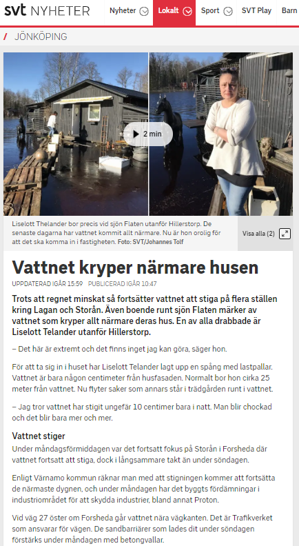

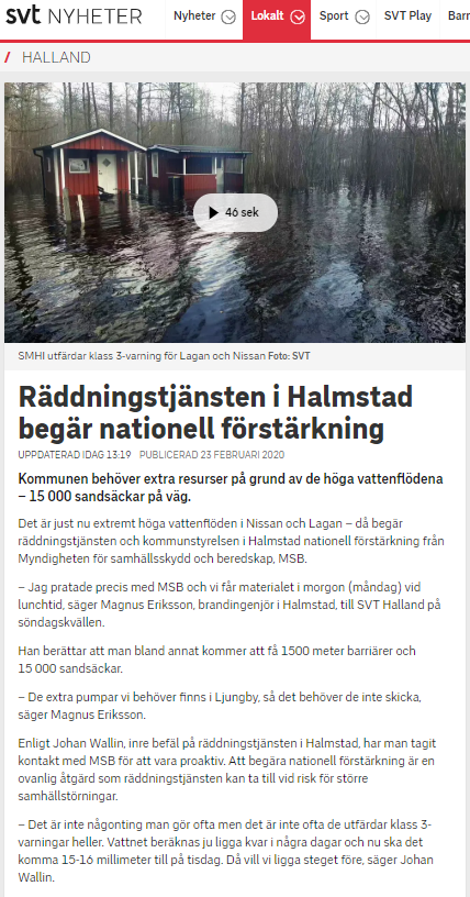
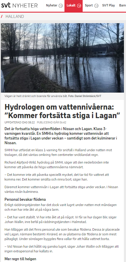

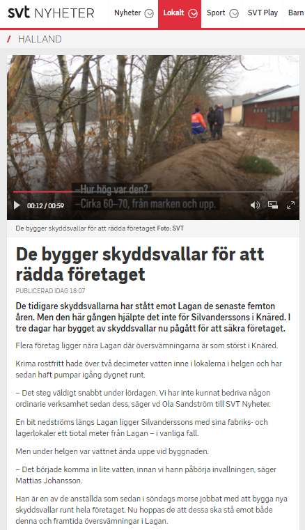
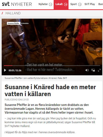

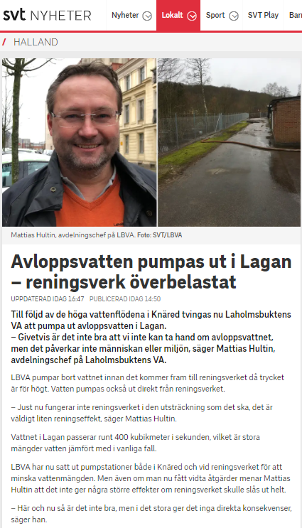


![MP_kontor_99493_WTC Oceanhamnen_Bröderna Pihls gränd_västerbild ([3149][@[resize:5200,2930][crop:34,0,5021,2919][autoorient:][background:%23ffffff][quality:80][strip:][extension:jpg][id:7]]).jpg](https://www.wtcmalmolundhelsingborg.se/siteassets/qbank/mp_kontor_99493_wtc-oceanhamnen_broderna-pihls-grand_vasterbild-3149resize52002930crop34050212919autoorientbackground23ffffffquality80stripextensionjpgid7.jpg?width=1010&height=630&scale=both&mode=crop)