Borstlösa DC-motorer, eller BLDC-motorer, är strömhungriga, kraftfulla motorer som blir allt vanligare i olika applikationer. Vi hittar dem i allt från radiostyrda fordon, drönare, elcyklar, maskiner och robotar. De är dyrare än DC-motorer och de kräver en betydligt mer avancerad styrning, men är å andra sidan överlägsna när det kommer till prestanda och kontroll av hastighet, acceleration och vridmoment.
En traditionell DC-motor börjar snurra så fort man kopplar en spänningskälla till de två anslutningarna. En BLDC-motor, som har tre separata strömmatningsanslutningar, behöver däremot en ESC (Electronic Speed Controller) för att fungera.
I följande filmklipp får du en introduktion till hur BLDC-motorer fungerar, samt hur man kontrollerar deras hastighet med en ESC. Filmen tar även upp hur en Arduino kan användas för att styra ESC:n så att varvtal och rotationsriktning av motorn kan kontrolleras via en programvara.
How Brushless Motor and ESC Work and How To Control them using Arduino (12:45)
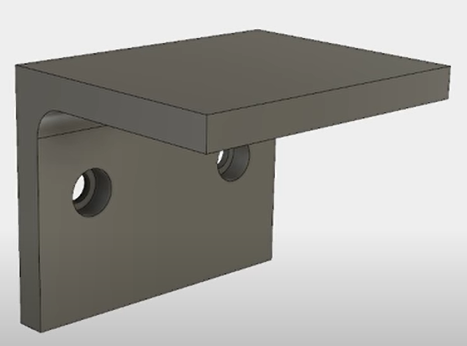
I följande instruktionsfilm av Lars Christensen får du lära dig hur du steg för steg gör en belastningssimulering i Fusion 360. I exemplet används en hyllkonsol i form av en L-vinkel, och din CAD-uppgift är att rita en liknande L-vinkel och sedan utföra samma typ av belastningssimulering som visas i instruktionsfilmen. En viktig fördel med att använda 3D-CAD i sitt konstruktionsarbete är att man enkelt kan testa hur olika material och variation på designen påverkar en produkts hållfasthet, genom att simulera lasterna i datorn.
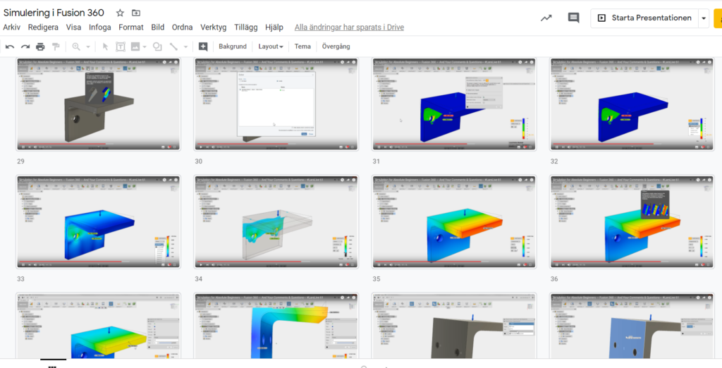
Simulation for Absolute Beginners — Fusion 360 — And Your Comments & Questions— #LarsLive 61 (41:16)
Här nedan har jag gjort en sammanställning av instruktionsfilmens olika steg för att du snabbt och enkelt ska kunna repetera och hitta de inställningar du behöver när det är dags för dig att göra dina egna simuleringar. Kommentarerna gör det lättare att komma ihåg och förstå vad de olika delarna innebär.
Skapa en 3D-modell av hyllkonsolen. För att ha något att simulera med så behöver du skapa en liknande hyllkonsol som i instruktionsfilmen. Börja med att CAD:a en L-formad vinkel i valfri godstjocklek. Du gör alltså en 2D-sketch som du sedan extruderar till 3D. Lägg till en rundad avfasning (chamfer) på undersidan av 90-gradersvinkeln. Rita in två hål för skruvar för infästning mot väggen. Skruvhålen ska ha en infällning för skruvskallarna på ungefär halva godstjockleken på djupet och ungefär dubbla diametern i förhållande till hålens diameter.
3D-modell av en hyllkonsol
Olika typer av simulering i Fusion 360
Olika typer av simuleringsstudier i Fusion 360
Static Stress är den enklaste typen av simulering. Det handlar om att applicera en last på någonting. Det kan t ex vara att sätta en vikt på ett hyllplan, slå till en yta med en hammare (impact) eller en belastning som trycker på en balk. Det fungerar på t ex metall, men inte för mjuka material som gummi eller plast. Dessa behöver NonLinear Static Stress.
Modal Frequencies används för att simulera vibrationer och dess frekvenser som t ex kan ge upphov till buller och förslitningsskador på lager vid obalans för roterande delar som fläktar, axlar och hjul.
Med en Thermal Study kan du simulera vad som händer med materialen när de utsätts för värme.
En Thermal Stress Study simulerar vad som händer med komponenterna när de utsätts för både värme och strukturell mekanisk belastning.
En Structural Buckling Study simulerar hur komponenterna deformeras och böjs vid belastning (de går inte av eller bryts sönder).
Nonlinear Static Stress är ett kraftfullt simuleringsverktyg som bl a kan användas för plaster och gummi där belastningen och materialens påverkan varierar över ytan och även över tid.
Event simulation handlar om att se hur ett material eller konstruktion påverkas över tid och efter multipla belastningscykler. Man kan simulera hur många gånger en mekanisk rörelse kommer fungera innan materialet utmattats och går sönder.
Shape Optimization är ett simuleringsverktyg som automatiskt kan designa en komponent eller konstruktion efter vissa kriterier. Om du t ex specificerar vilka krafter som konstruktionen ska tåla så ritar Shape Optimization-verktyget upp hur delen ska konstrueras beträffande godstjocklek etc.
Sammanfattning av de olika stegen för att göra en statisk simulering
Välj simuleringstyp (Static Stress)
Lägg till en mesh till din modell/konstruktion/part
Ställ in så att du har fler är två trianglar på höjden av sidan på den delen som du ska belasta.
Definiera vilka constraints du vill ha. I detta fall Fixed i förhållande till den del av din modell som kommer hållas på plats av skruvar mot väggen.
Lägg till en last (Force), definiera vilken yta/plan som ska belastas, kraftens riktning, storlek och enhet.
De senaste åren har det skrivits mycket om att robotar tar människors jobb. Allt fler arbetsuppgifter ersätts av robotar, och fler står på tur i takt med att robotarna snabbt blir bättre och mer avancerade.
I robotiseringens och automatiseringens kölvatten skapas dock mängder av nya arbetstillfällen, främst inom teknikyrken som programmering, AI och mekatronik.
Här är dock ett intressant filmklipp från Japan som visar hur ett café erbjuder människor med funktionsnedsättningar arbetstillfällen som robotservitörer. Robotarna i caféet fjärrstyrs helt enkelt av människor som kan sitta eller ligga hemma och styra dem och interagera med caféets besökare. Mänsklig social interaktion och social integrering möjliggörs tack vara robotarna.
Robotar som ger människor jobb
Uppgifter och diskussionsfrågor
Vad tycker du om det du såg på filmen? Hur känner du inför en utveckling där allt fler mänskligt fjärrstyrda robotar interagerar med oss i offentliga miljöer som t ex caféer eller butiker?
Ge exempel på negativa saker med mänskligt fjärrstyrda robotar som interagerar med oss i offentliga miljöer.
Ge exempel på positiva saker med mänskligt fjärrstyrda robotar som interagerar med oss i offentliga miljöer.
Tycker du att denna typ av arbetsuppgift enbart ska utföras av människor med olika typer av funktionsnedsättningar? Eller bör det vara som vilken typ av jobb som helst att alla får konkurrera om jobben på lika villkor?
Skulle du hellre vilja bli serverad av en mänskligt fjärrstyrd servitörsrobot eller en autonom robot som styrs automatiskt av artificiell intelligens eller utifrån förprogrammerade instruktioner?
Hur tycker du att en servitörsrobot ska se ut? Ska den likna roboten i filmen? Ska den likna en människa mer? Tycker du att den ska se helt annorlunda ut och kanske vara mer anpassad för att hämta och lämna brickor eller tallrikar och glas? Beskriv, skissa och sök gärna efter inspiration på Internet.
Vilka egenskaper behöver en bra servitörsrobot ha? Vad ska den kunna göra? Beskriv funktionerna och hur den rent mekaniskt ska vara uppbyggd. Vilka funktioner behöver programmeras? Vilka funktioner behöver fjärrstyras? Hur kan man lösa de olika funktionerna rent tekniskt?
Skulle du kunna tänka dig att jobba med denna typ av teknologi själv? Hur då i så fall? Som den som styr roboten, som den som programmerar den eller som den som konstruerar och designar den här typen av robotar?
Ett stort problem inom skolans värld är att olika IT-system inte fungerar tillsammans eller att en massa information behöver läggas in flera gånger i olika system eftersom de inte automatiskt kan dela information mellan sig. Det beror oftast på att det saknas smarta och enhetliga sätt att definiera den information som systemen ska hantera eller hur kommunikationen mellan olika system ska ske. För att lösa sådana problem brukar man ta fram och sedan hålla sig till standarder. Nu har Sverige äntligen fått igång ett arbete som syftar till att definiera vilka IT-standarder som är av relevans för skolan.
Tillsammans med Skolverket, SIS, flera huvudmän och i samband med ett Vinnova-finansierat projekt om standarder för datadrivna processer, har Swedish Edtech Industry påbörjat ett arbete att ta fram en lista över de standarder och rekommendationer som finns och som är aktuella för att skapa ett säkert, effektivt, kvalitativt digitalt ekosystem för det svenska skolväsendet. En kort sammanfattande information om detta arbete och vad standarder innebär kan läsas nedan. Men för mer information och för löpande aktuell information om arbetet rekommenderas läsning direkt från ursprungskällan på Edtechkartan.se. Edtechkartan.se som lanserades hösten 2018 är en systemkarta över det svenska edtech-landskapet med inriktning på skolväsendet. Det är en interaktiv och lättanvänd digital systemkarta som löpande kommer att hållas uppdaterad. Kartan tar utgångspunkt i skolans och skolhuvudmannens verksamhetsprocesser och utifrån dessa verksamhetsområden mappas leverantörer in som idag har lösningar för att stödja processen. Det har hittills inte funnits en mer detaljerad bild över det komplexa digitala ekosystemet som utbildningssektorn utgör.
Interoperabilitet och it-standarder
Alla dessa standarder
Kravställ för interoperabilitet, kravställ standarder! En enkel uppmaning, men inte lika enkel att genomföra. Begreppet standard tolkas på olika sätt och det är viktigt att peka på vad vi menar och vad skillnaderna är. Det finns nationella och internationella standarder, det finns rekommendationer som i princip anses vara standarder men med olika “dialekter”(där rekommendationerna tolkas och används på olika sätt). Vi är alla överens om behovet av att etablera standarder, göra dem vedertagna för ett kvalitetssäkrat digitalt ekosystem, för ett ett säkert och effektivt informationsflöde, för interoperabilitet. Men om standarder inte beställs, så testas och implementeras de inte. Man ska också vara medveten om att standarder blir gamla och det finns risk för cementering av it-miljöerna. Alltså behöver vi alla hela tiden vara uppmärksamma, föra dialog och tillsammans se till att de standarder som finns är aktuella.
Det är också viktigt att inte blanda ihop vad som är en standard och vad som är en faktisk lösning. En standard beskriver och definierar. En lösning levererar (och det finns således alltid en leverantör bakom).
I december 2019 etablerades ett nationellt forum för arbetet med standarder: Forum för informationsstandardisering i skolväsendet. Ett forum Skolverket ansvarar för, i samverkan med olika aktörer, däribland Swedish Edtech Industry.
Vad är egentligen en “standard”?
En teknisk standard är en specifikation av ett format som tas fram, förvaltas och tillhandahålls av en standardiseringsorganisation, men en standard kan också vara en överenskommen definition av ett begrepp eller ord (klass, grupp o.s.v.). Standarder utvecklas vanligen genom frivilliga överenskommelser. Ett givet format kan vara erkänt av fler än en organisation och det finns format som inte erkänts av någon standardiseringsorganisation.
SIS, Svenska institutet för standarder, definierar begreppet standard så här:
En standard är en smart gemensam lösning på ett återkommande problem. Syftet med standarder är att skapa enhetliga och transparenta rutiner som vi kan enas kring.
Standarder kopplat till lärande, kommer ofta i paket med olika delar och är mer eller mindre heltäckande. Det finns olika organisationer som arbetar med olika former av “standardpaket”:
– ISO, International organization för standardization. Levererar internationella standarder, där delar kan användas och andra anpassas enligt lokala (nationella) behov inom specifika områden.
– SIS, Svenska institutet för standarder. Arbetar i tekniska kommittéer där standarder tas fram kopplat till olika områden, varav TK450 är en kommitté med fokus på standarder för it och lärande. I TK450 ingår flera olika arbetsgrupper där en arbetsgrupp t.ex. tagit fram SS12000, en annan EMIL (Education Information Markup Language). Speglar det internationella arbetet i ISO och gör nationella anpassningar.
– IMS Global Learning Consortium – levererar olika rekommendationer som sedan tolkas och anpassas. Ibland brukar man säga att IMS rekommendationer har olika “dialekter”. Ett exempel är IMS LTI (Learning Tools Interoperability), en “standard” (rekommendation) för anslutning av externa webbaserade lärresurser och innehåll till andra plattformar.
Stöd i arbetet: en lista med standarder
Tillsammans med Skolverket, SIS, flera huvudmän och i samband med ett Vinnovafinasierat projekt om standarder för datadrivna processer, har vi påbörjat en lista över de standarder och rekommendationer samt några relevanta informationsflöden som finns och som är aktuella för att skapa ett säkert, effektivt, kvalitativt digitalt ekosystem.
Denna listning har vi inom ramen för det här projektet gått igenom och mappat gentemot de olika områden och processer som finns definierade i edtechkartan. Vi har också gjort en ansats till att visa vilka standarder som aktuella respektive inaktuella, eftersom det är viktigt att inte fastna i äldre teknik eller i standarder som i sin tur kan bli cementerande.
I nedan länkat kalkylark finns listningen + områden & processer + definitioner och lite annat smått och gott som vi hoppas är till nytta i arbetet med kravställningar. Dokumentet ska ses som ett arbetsdokument, öppet för alla att kommentera i, så gör gärna det. Tillsammans kan vi göra det mer komplett och hålla det uppdaterat.
Blender 2.8 Facial motion capture tutorial In this blender 2.8 tutorial by CGMatter we go over how we can use blender as a free facial motion capture solution. Track facial performance using just tracking markers and blender!
In this blender 2.8 tutorial, by CGMatter (https://www.cgmatter.com), we go over the fundamentals of motion tracking inside blender. Specifically we go over image sequence conversion and the motion models (location, rotation, scale, affine, perspective) used for tracking. This is the first part of a 3 part tutorial series covering everything to do with motion tracking. TIMESTAMPS: 00:00:00 – Introduction 00:01:18 – What is motion tracking? 00:01:55 -Image sequences (theory + conversion) 00:08:33 – Switching to movie clip editor 00:10:05 – Setting up 00:11:46 – Location tracking (and some basics) 00:16:43 – Tracking panel (track speed, frames limit, etc) 00:19:16 – Search area and pattern area (optimization) 00:22:20 – Default settings vs local settings 00:23:03 – Modifying the pattern area 00:24:33 – Graphs (how to interpret X and Y data) 00:26:10 – Link empty to track 00:27:33 – Basic 3d integration 00:28:37 – Location rotation motion model (+ comparing to location model) 00:33:10 – What a tracker really stores 00:33:58 – 2 point tracking (for rotation/scaling data) 00:39:20 – Normalize 00:42:16 – Location rotation scale motion model 00:46:17 – Previous frame vs keyframe (match mode) 00:48:47 – Correlation (with a small mistake :D) 00:53:03 – Affine motion model 01:00:19 – Perspective motion model 01:13:03 – RGB color channels 01:15:10 – Closing thoughts + sneak-peek
Blender 2.8 Motion tracking #2: Even more to go over (tutorial)
In this blender 2.8 tutorial we continue developing the theory of motion tracking by going over techniques like join tracks and offset tracking. We also talk about applications like masking, plane tracks, stabilization, and compositing. TIMESTAMPS: 00:00:00 – Introduction (what we’ll go over) 00:01:11 – Setup 00:02:35 – Obstructions (join tracks) 00:08:23 – Offset tracking 00:14:52 – Stabilization (lot’s of stuff in here) – multiple trackers – stab weight – rotation/scale 00:23:21 – Color coding 00:24:36 – More stabilization – autoscale – anchor frame 00:26:51 – Compositing (stabilize 2d node) 00:32:32 – Rendering stabilized result 00:35:23 – Plane track 00:42:30 – Compositing (plane track deform node) – masking – dilate/erode node 00:49:44 – Manual hook approach 00:57:12 – Masking 01:00:16 – Mask node (compositing) 01:01:37 – Overview + sneak-peek
Blender 2.8 Motion tracking #3: Camera tracking in depth (tutorial)
In this blender 2.8 tutorial we finally go over camera tracking and the theory involved in reducing your solve error. We also talk about orientation and compositing which lets us put 3d objects in our scene.
Blender 2.8 Motion tracking #4: Camera tracking examples (tutorial)
In this blender 2.8 tutorial we review what we’ve learned about camera tracking. Specifically we try to get a good camera solve on two new shots one of which is a tripod shot.
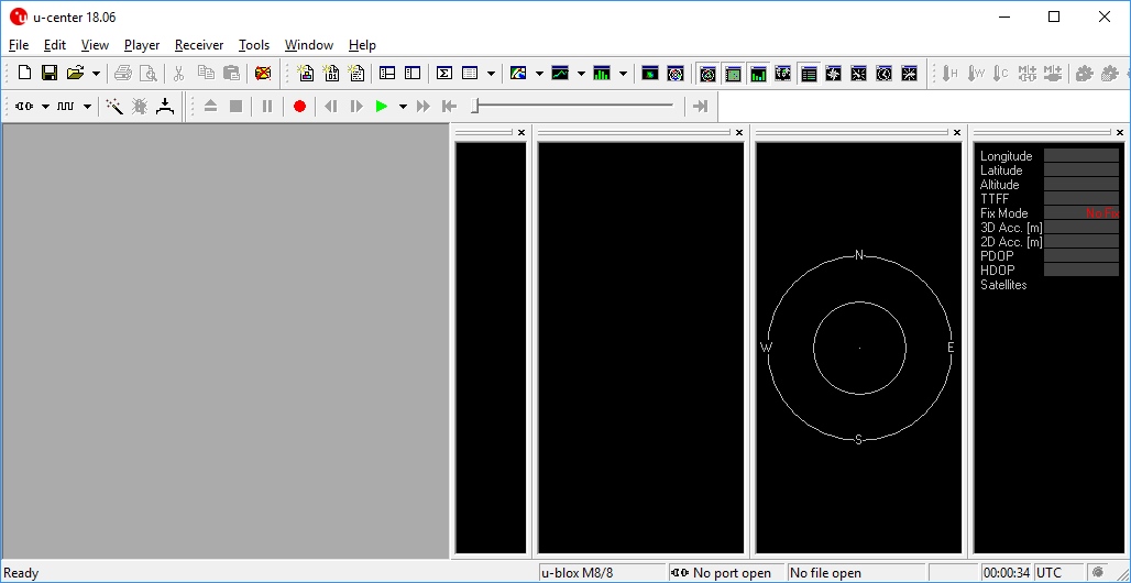
U-center from u-blox is a free software tool for configuring u-blox GPS receivers under Windows. U-center is a dense program with many interface elements. It can be overwhelming at first but over time it will become easier to use. For all its GUI weaknesses, it is very powerful for configuring the u-blox line of modules (such as the NEO-M8P-2 and SAM-M8Q to name a few). In this tutorial, we will be exploring some of its features with the NEO-M8P-2.
Required Software
The software can be obtained from u-blox. To follow along with this tutorial please download and install u-center. Once completed, open it.DOWNLOAD U-CENTER
Install Drivers
For this tutorial we’ll assume you have the SparkFun GPS-RTK but u-center can be used with any u-blox based product. Start by attaching a micro-B cable to the GPS-RTK board.
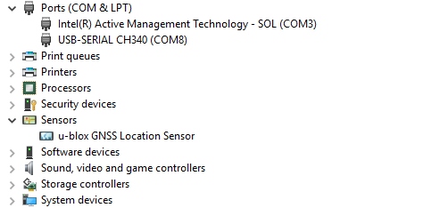
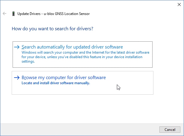
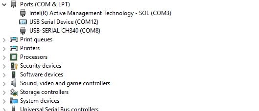
Now open Windows Device Manager. The NEO-M8 series has an annoying feature where the module comes up as a Windows Sensor rather than a serial device. If your u-blox receiver does not appear under COM ports then right click on the u-blox GNSS Location Sensor and then Update Driver. Next, click on Browse my computer for driver software.
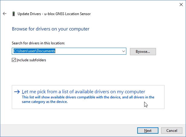
Then “Let me pick”…
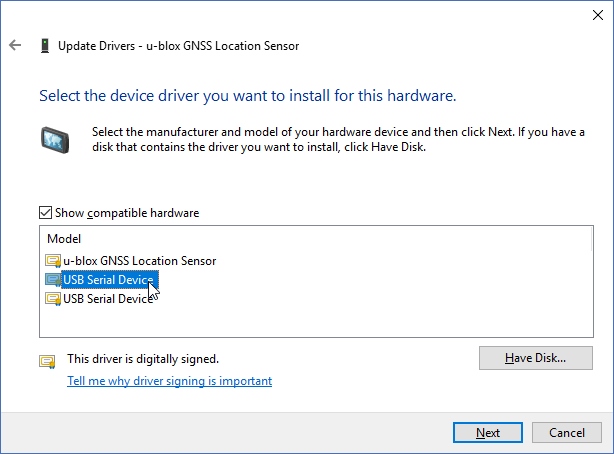
Select the first USB serial device.
The SparkFun GPS-RTK board should now enumerate as a USB serial COM port. In the list below, the GPS-RTK board is COM12.
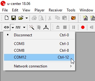
Return to u-center and drop down the port list. Select the COM port that is your RTK board. Congrats! You can now use u-center.
Configuring and Outputting NMEA Sentences
Let’s go over a few features you’ll likely use:
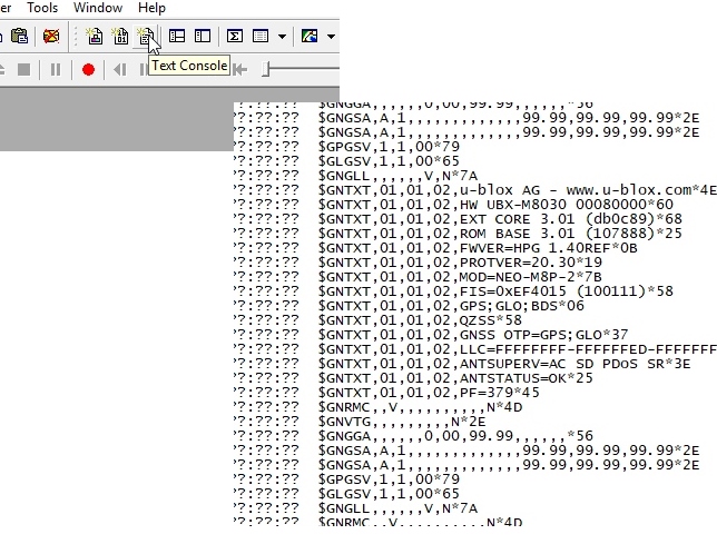
Text Console
The text console button will show you the raw NMEA sentences. This is handy for quickly inspecting the visible ASCII coming from the module over USB.
Configure
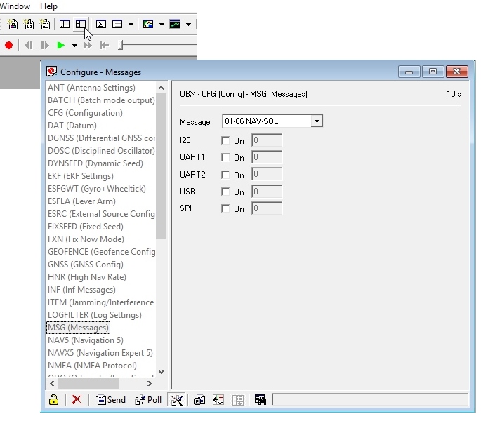
The configuration button opens the most powerful window. From this window you can inspect and configure new settings. It’s not obvious but when you click on a setting such as ‘MSG (Messages),’ u-center will poll the module for its current state. The ‘10s’ in the corner indicates how old the displayed information is. In this case it’s been 10 seconds since this setting was last queried. Click on the ‘Poll’ button to update the information. Go ahead and select the F0-00 NMEA GxGGA message. As you click the dropdown menu, the software will poll the current settings. It’s a bit disorienting at first but gets better over time.
The MSG configuration is very powerful. It allows you to enable or disable various NMEA sentences as well as binary protocols such as NAV-PVT (checkout the [full protocol datasheet](link text). Once a sentence is selected, such as GxGGA, the check boxes will be populated. If you want to disable the GxGGA sentence for the SPI interface, uncheck the SPI checkbox and then click ‘Send’. Congrats! The GxGGA sentence is no longer presented on the SPI interface. This raises an important fact:
Note: The NEO-M8 series has 4 interfaces: USB(serial), I2C, SPI, and UART. All interfaces can access information simultaneously. This means you can inspect configuration settings over the USB serial port while your Arduino makes setting changes over the I2C port. You can read NMEA sentences over the I2C port or send RTCM data into the module over SPI. It’s all highly configurable.
What is the USB Port on the NEO-M8P?
It’s like any other USB to serial device. It will enumerate on your computer as a COM port and acts as such. It is independent and separate from the UART port that is a dedicated TTL serial port.
If something is not accessible through u-center, it probably means that feature or setting is not compatible with the currently attached device. For example, the UART2 box is grayed out in the image above. The NEO-M8P does not have a second UART so you can’t address it.
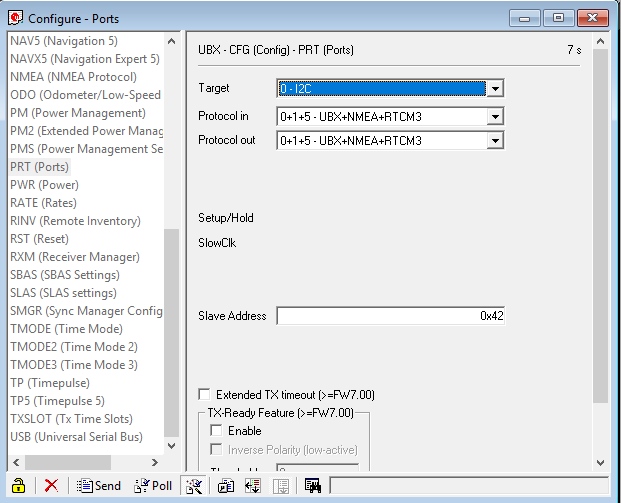
Ports
The Ports (PRT) sub-menu under Configuration is very helpful. You can do things like change the baud rate, I2C address, and protocols. Depending on your application, you may want to enable or disable entire interface protocols. For example, if you want to enable NMEA sentences for the SPI interface, you would do it here. Fortunately, the factory default for the NEO-M8P is good for I2C and UART1 for RTK purposes (input of RTCM3 is enabled for both ports).
This is also the menu that allows you to change the I2C address of your GPS-RTK. Because we are big fans of the Qwiic system, we’ll be using the GPS-RTK on the I2C bus. If we had another device on the bus that uses address 0x42 this menu will allow us to change the address of the GPS-RTK.
Poke around the various config menus. If you get your module into an unknown state you can unplug and replug to reset the settings.
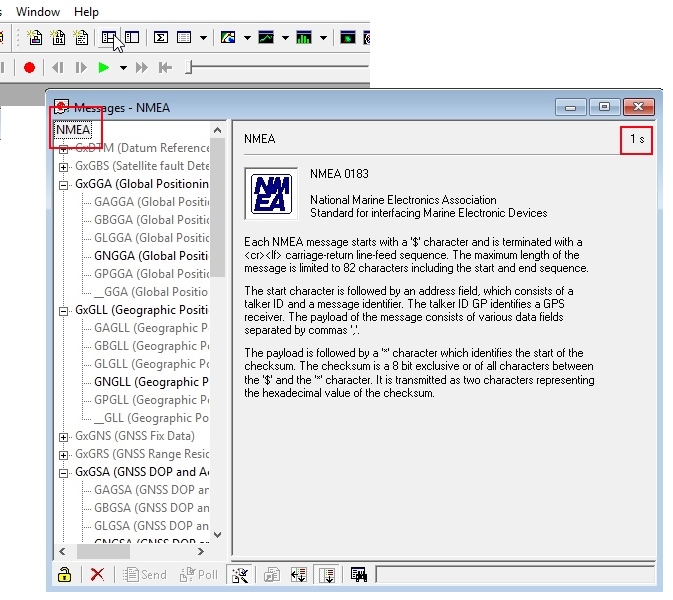
Messages
The messages window will allow you to view the various sentences reported by the module. It’s not obvious but if you double click on ‘NMEA’, the tree of messages will fold away. Similarly, if you double click on ‘UBX’, it will expand showing the various UBX sentences. By default, many of these are not enabled.
Resources and Going Further
Ready to get hands-on with GPS?
We’ve got a page just for you! We’ll walk you through the basics of how GPS works, the hardware needed, and project tutorials to get you started.
Once you’ve mastered U-Center you’re ready to begin configuring your Ublox module! Check out some of these related tutorials:Building an Autonomous Vehicle: The BatmobileDocumenting a six-month project to race autonomous Power Wheels at the SparkFun Autonomous Vehicle Competition (AVC) in 2016.GPS-RTK Hookup GuideFind out where you are! Use this easy hook-up guide to get up and running with the SparkFun high precision GPS-RTK board.GPS-RTK2 Hookup GuideGet precision down to the diameter of a dime with the new ZED-F9P from Ublox.
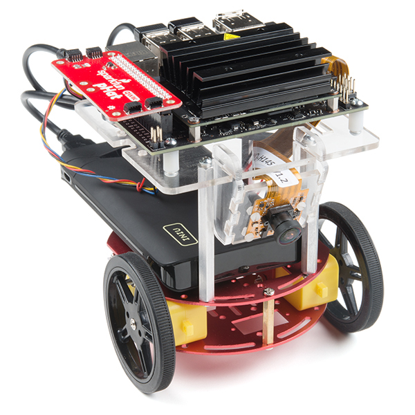
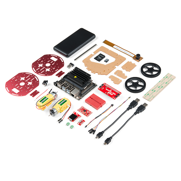
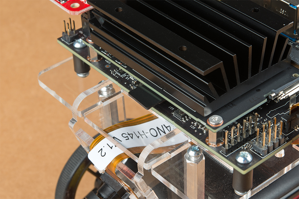
SparkFun’s version of the JetBot merges the industry leading machine learning capabilities of the NVIDIA Jetson Nano with the vast SparkFun ecosystem of sensors and accessories. Packaged as a ready to assemble robotics platform, the SparkFun JetBot Kit requires no additional components or 3D printing to get started – just assemble the robot, boot up the Jetson Nano, connect to WiFi and start using the JetBot immediately. This combination of advanced technologies in a ready-to-assemble package makes the SparkFun JetBot Kit a standout, delivering one of the strongest robotics platforms on the market. This guide serves as hardware assembly instructions for the two kits that SparkFun sells; Jetbot including Jetson Nano & the Jetbot add-on kit without the NVIDIA Jetson Nano. The SparkFun JetBot comes with a pre-flashed micro SD card image that includes the Nvidia JetBot base image with additional installations of the SparkFun Qwiic Python library, Edimax WiFi driver, Amazon Greengrass, and the JetBot ROS. Users only need to plug in the SD card and set up the WiFi connection to get started.
Note: We recommend that you read all of the directions first, before building your Jetbot. However, we empathize if you are just here for the pictures & a general feel for the SparkFun Jetbot. We are also those people who on occasion void warranties & recycle unopened instructions manuals. However, SparkFun can only provide support for the instructions laid out in the following pages.
Attention: The SD card in this kit comes pre-flashed to work with our hardware and has the all the modules installed (including the sample machine learning models needed for the collision avoidance and object following examples). The only software procedures needed to get your Jetbot running are steps 2-4 from the Nvidia instructions (i.e. setup the WiFi connection and then connect to the Jetbot using a browser). Please DO NOT format or flash a new image on the SD card; otherwise, you will need to flash our image back onto the card.
If you accidentally make this mistake, don’t worry. You can find instructions for re-flashing our image back onto the SD card in the software section of the guide
The Jetson Nano Developer Kit offers extensibility through an industry standard GPIO header and associated programming capabilities like the Jetson GPIO Python library. Building off this capability, the SparkFun kit includes the SparkFun Qwiic pHat for Raspberry Pi, enabling immediate access to the extensive SparkFun Qwiic ecosystem from within the Jetson Nano environment, which makes it easy to integrate more than 30 sensors (no soldering and daisy-chainable).
The SparkFun Qwiic Connect System is an ecosystem of I2C sensors, actuators, shields and cables that make prototyping faster and less prone to error. All Qwiic-enabled boards use a common 1mm pitch, 4-pin JST connector. This reduces the amount of required PCB space, and polarized connections mean you can’t hook it up wrong.
Materials
The SparkFun Jetbot Kit contains the following pieces; roughly top to bottom, left to right.
Part
Qty
Circular Robotics Chassis Kit (Two-Layer)
1
Lithium Ion Battery Pack – 10Ah (3A/1A USB Ports)
1
Ball Caster Metal – 3/8″
1
Edimax 2-in-1 WiFi and Bluetooth 4.0 Adapter
1
Header – male – PTH – 40 pin – straight
1
2 in – 22 gauge solid core hookup wire (red)
1
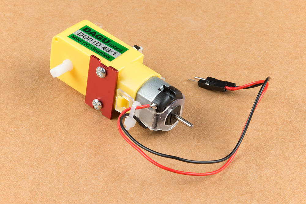
Shadow Chassis Motor (pair)
1
Jetson Dev Kit (Optional)
1
SparkFun JetBot Acrylic Mounting Plate
1
SparkFun Jetbot image (Pre Flashed)
1
Leopard Imaging 145 FOV Camera
1
Screw Terminals 2.54mm Pitch (2-Pin)
2
SparkFun Micro OLED Breakout (Qwiic)
1
SparkFun microB USB Breakout
1
SparkFun Serial Controlled Motor Driver
1
Breadboard Mini Self-Adhesive Red
1
SparkFun Qwiic HAT for Raspberry Pi
1
SparkFun JetBot Acrylic sidewall for camera mount
2
SparkFun JetBot Acrylic Camera mount & 4x nylon mounting hardware
1
Qwiic Cable – 100mm
1
Qwiic Cable – Female Jumper (4-pin)
1
Wheels & Tires – included as part of circular robotics chassis
2
USB Micro-B Cable – 6″
2
Dual Lock Velcro
1
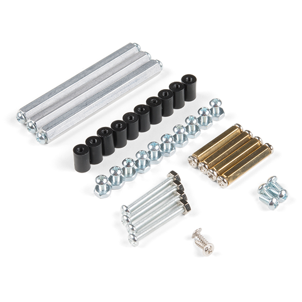
The SparkFun Jetbot Kit contains the following hardware; roughly top to bottom, left to right.
We did not include any tools in this kit because if you are like us you are looking for an excuse to use the tools you have more than needing new tools to work on your projects. That said, the following tools will be required to assemble your SparkFun Jetbot.
Small phillips & small flat head head screwdriver will be needed for chassis assembly & to tighten the screw terminal connections for each motor. We reccomend the Pocket Screwdriver Set; TOL-12268.
Pair of scissors will be needed to cut the adhesive Dual Lock Velcro strap to desired size; recommended, but not essential..
Soldering kit for assembly & configuration of the SparkFun Serial Controlled Motor Driver – example TOL-14681
Optional– adjustable wrench or pliers to hold small components (nuts & standoffs) in place while tightening screws; your finger grip is usually enough to hold these in place while tightening screws & helps to ensure nothing is over tightened.A Note About Directions
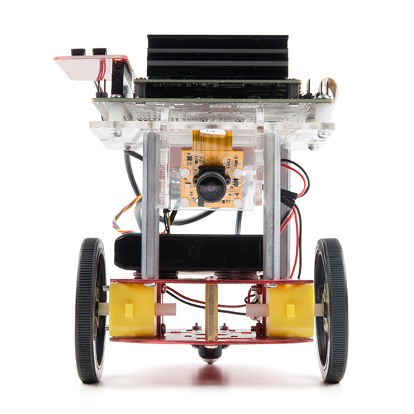
When we talk about the ”front,” or ”forward” of the JetBot, we are referring to direction the camera is pointed when the Jetbot is fully assembled. ”Left” and ”Right” will be from the perspective of the SparkFun Jetbot.
If you prefer to follow along with a video, check out this feature from the chassis product page. You do not need to use the included ball caster as a larger option has been provided for smoother operation.
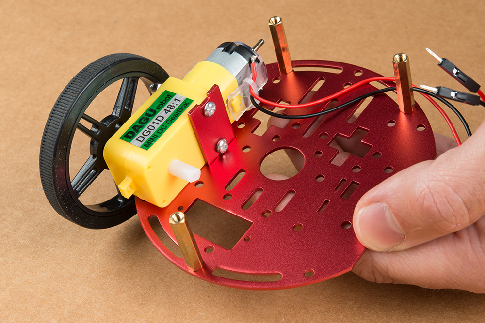
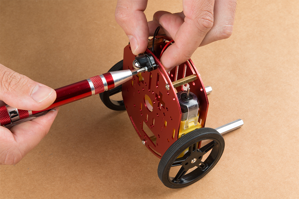
Start by attaching the chassis motor mount tabs to each of the ”Shadow Chassis Motors (pair)” using the long threaded machine screws & nuts included with the Circular Robotics Chassis Kit.
Fit the rubber wheels onto the hubs, install the wheel onto each motor, & fix them into position using the self tapping screws included with the Circular Robotics Chassis Kit.
Install the brass colored standoffs included with the Circular Robotics Chassis Kit; two in the rear and one in the front. The rear of the SparkFun Jetbot will be on the side of the plate with the two ”+” sign cut outs. The rear of the motor will be opposite the wheel where the spindle extends. This orientation ensures the widest base & most stable set up for your Jetbot.
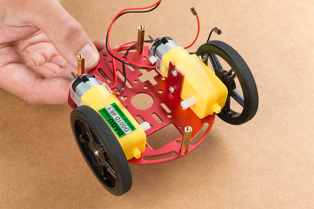
The motor mounts fit into two mirrored inlets in each base plate as shown. Install the motors opposite of one another.
Depending on how you install the motor mounts to each motor will dictate how the motor can be installed on the base plate. Note: Do not worry about the motor orientation as you will determine proper motor operation in how you connect the motor leads to the SparkFun Serial Controlled Motor Driver. Notice how in the picture below one motor has the label facing up, while the other has the label facing down.
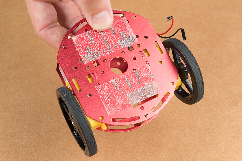
Place the other circular robot chassis plate on top of and align the two ”+” and the motor mount tab recesses. Hold the sandwiched chassis together with one hand and install the remaining Phillips head screws included with the Circular Robotics Chassis Kit through the top plate & into the threaded standoffs.
Your main chassis is now assembled! The Circular Robotics Chassis Kit also contains a very small caster wheel assembly, but we have included a larger metal caster ball to increase the stability of the SparkFun Jetbot. We will cover the installation of this caster ball later in the tutorial.
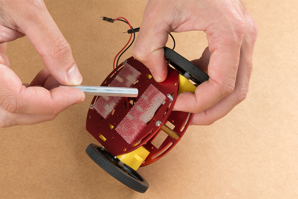
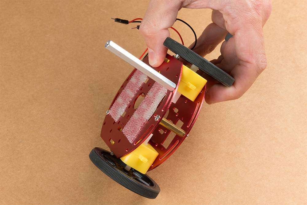
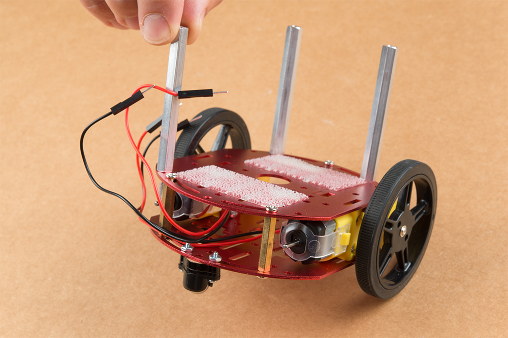
Utilize three of the included 1/4 in 4-40 Phillips Screws through the top chassis plate with threads facing up & install the 2-3/8 in #4-40 Aluminum Hex Standoff until they are finger tight.
The aluminum stand offs should be pointing up as shown below.
The SparkFun JetBot acrylic mounting plate is designed to have two of these aluminum standoffs in the front & one in the rear. We recommend the rear standoff on the left side of the chassis (as shown) so the 6 in microB usb cables that will be installed later can more easily span the gap needed to power the JetBot.
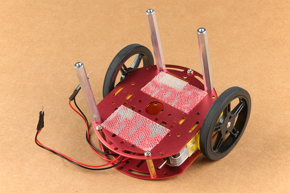
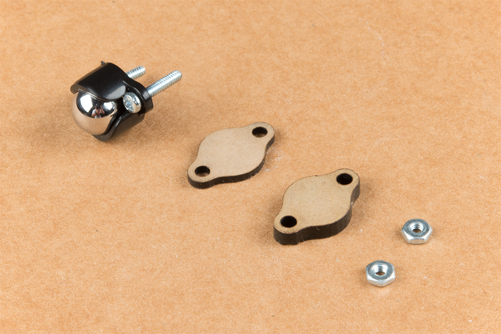
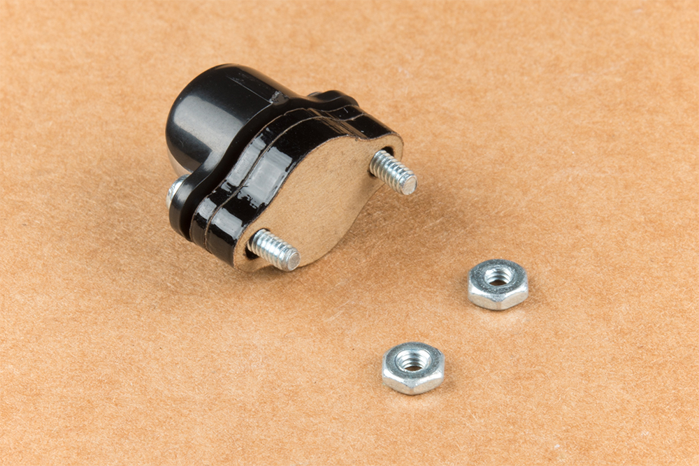
Un-package the 3/8 in Metal Caster Ball and thread the mounting screws through all pieces as shown. Note the full stack height will help balance the Jetbot in a stable position.
Install the caster wheel using the Phillips head screws and nuts included with the 3/8 in caster ball assembly. The holes on the caster assembly are spaced to fit snug on the innermost segment of the angular slots near the rear of the lower plate on the JetBot chassis. Again, hand tight is just fine. Note: if you over tighten these screws it will prevent the ball from easily rotating in the plastic assembly. However, too loose and it may un-thread; go for what feels right
After you have installed the caster & aluminum standoffs, thread the motor wires through the back of the chassis standoffs for use later.
2. Camera Assembly & Installation
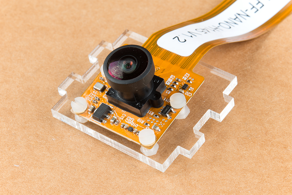
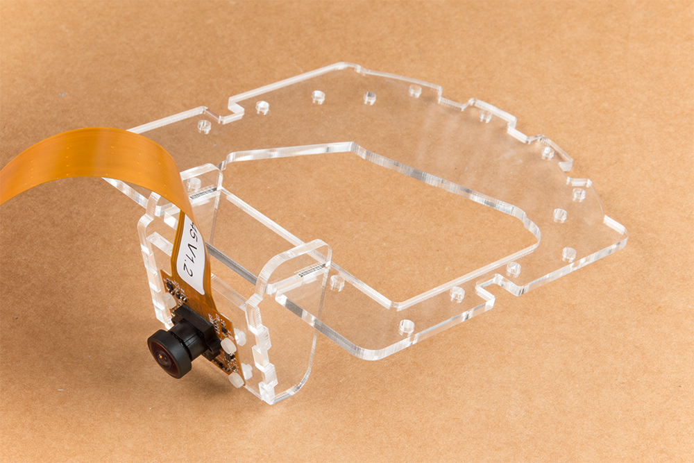
Unpackage the Leopard Imaging camera & align the four holes in the acrylic mounting plate with those on the camera.
Note: ensure that the ribbon cable is extending over the acrylic plate on the edge that does not have mounting holes near the edge; as shown below.
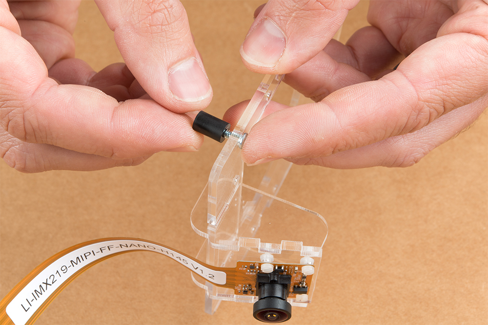
Place all four nylon flathead screws through the camera & acrylic mounting plate prior to fully tightening the nylon nuts. This will ensure equal alignment across all four screws. Tighten the screws while holding the nuts with finger pressure in a rotating criss cross pattern; similar to how you tighten lug nuts on a car rim.
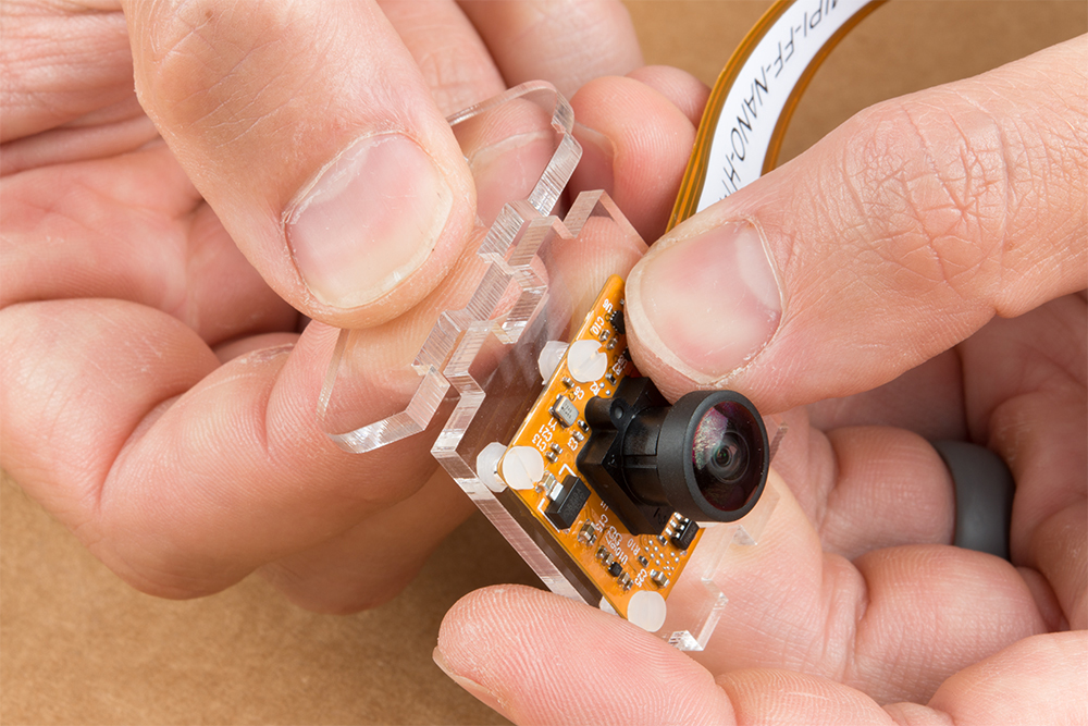
Align one acrylic sidewall with the camera mounting plate as shown below ensuring that the widest section of the sidewall is oriented to the top of the camera mount where the ribbon cable extends.
Apply even pressure on each piece until they fit together. Note: these pieces are designed to have an interference fit and will have a nice, satisfying ”click” when they fit together.
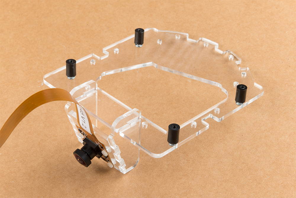
Repeat this process on the other side to fully assemble the camera mount.
The camera mount should now be installed to the SparkFun Jetbot acrylic mounting plate using the overlapping groove joints. Ensure that the cut out on the acrylic mounting plate is facing towards the front/right of the Jetbot as shown. This will ensure that there is plenty of room for the camera ribbon cable to pass around the assembly and up to the Jetson nano camera connector.
Install four of the nylon standoffs to the top of the SparkFun Jetbot acrylic mounting plate using four of the included 1/4 in 4-40 Phillips head screws as shown below.
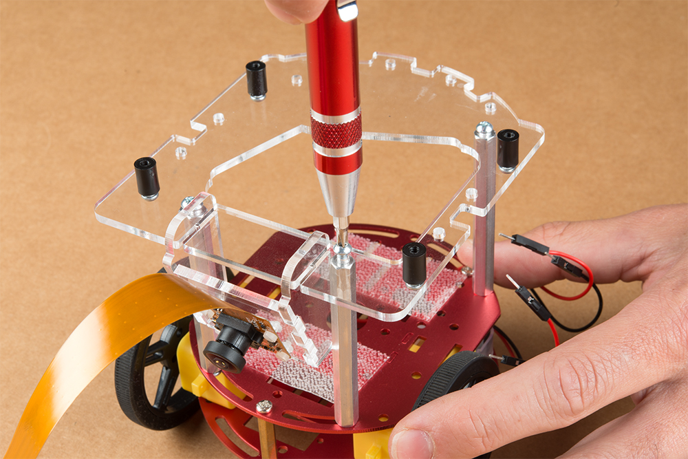
Utilize three more of the 1/4 in 4-40 Phillips head screws to install the SparkFun Jetbot acrylic mounting plate to the aluminum standoffs extending from the Two-layer circular robotics chassis as shown below.
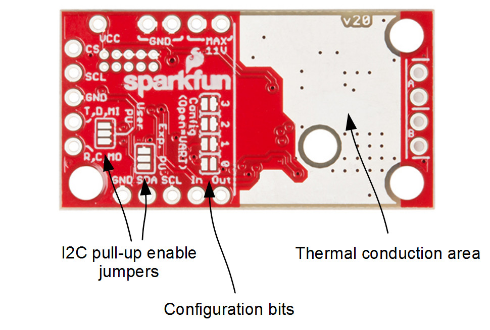
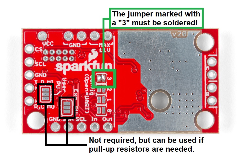
You will need to solder both triple jumpers labeled below as ”I2C pull-up enable jumpers” as the SparkFun pHat utilizes the I2C protocol. The default I2C address that is used by the pre-flashed SparkFun Jetbot image is 0x5D which is equavalent to soldering pad #3 noted as ”configuration bits” on the back of the SparkFun serial controlled motor driver; see below. You will need to create a solder jumper on pad #3 only for the SparkFun Jetbot Image to work properly.
Layout of jumpers on the Serial Controlled Motor Driver.
Jumper 3 of theConfiguration Bitsproperly soldered.
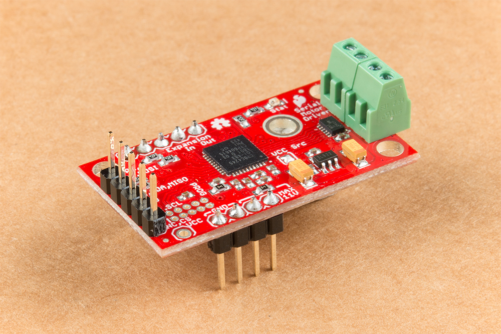
Your completed Serial Controlled motor drive should look somewhat similar to the board shown below.
The 2-pin screw terminals are soldered to the ”Motor Connections.”
Break off 4 Male PTH straight headers and solder into the ”Power (VIN) connection” points.
Break off 5 Male PTH straight headers and solder into the ”Expansion port” points. These will not be used, but will provide additional board stability when installed into the mini breadboard.
Break off 5 Male PTH straight headers and solder into the ”User port” points for connection into the included Female Jumper Qwiic cables.
Break off 5 Male PTH straight headers and solder into the breakout points on the SparkFun microB USB Breakout.
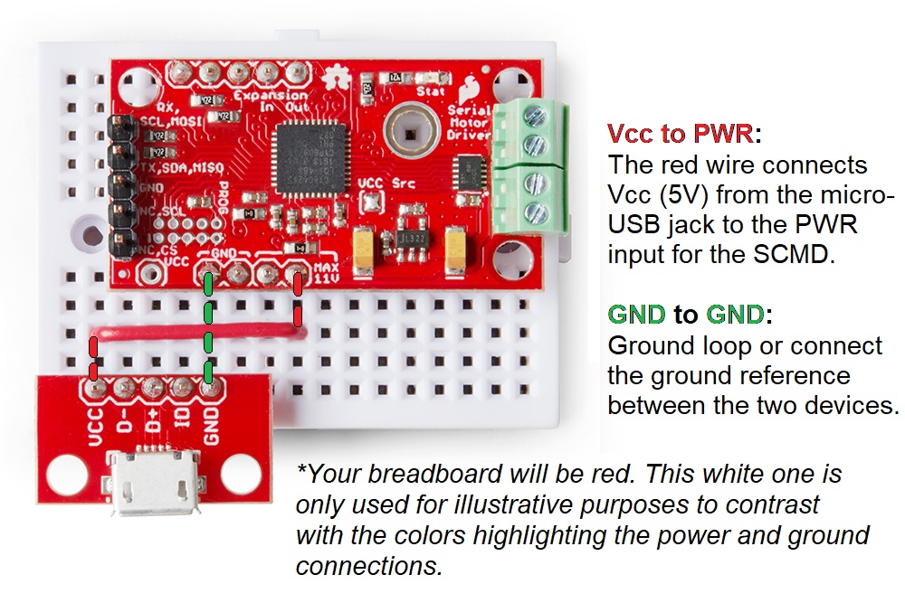
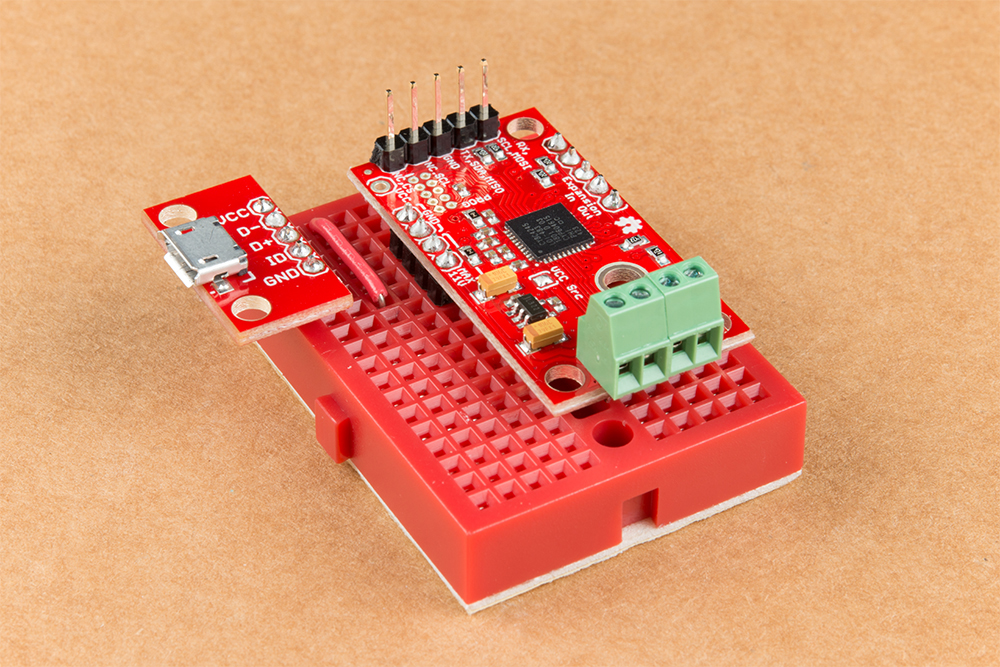
Install both the SparkFun Serial Controlled Motor Driver & the SparkFun microB Breakout board on the included mini breadboard so the ”GRD” terminals for each unit share a bridge on one side of the breadboard.
Utilize the included 2 in – 22 gauge solid core hookup wire (red) to bridge the ”VCC” pin for the SparkFun microB Breakout to either (VIN) connection point on the SparkFun Serial Controlled Motor Driver as shown below.
Required power connections between the micro-USB breakout and the Serial Controlled Motor Driver.
Competed assembly of the micro-USB breakout and Serial Controlled Motor Driver on the breadboard.
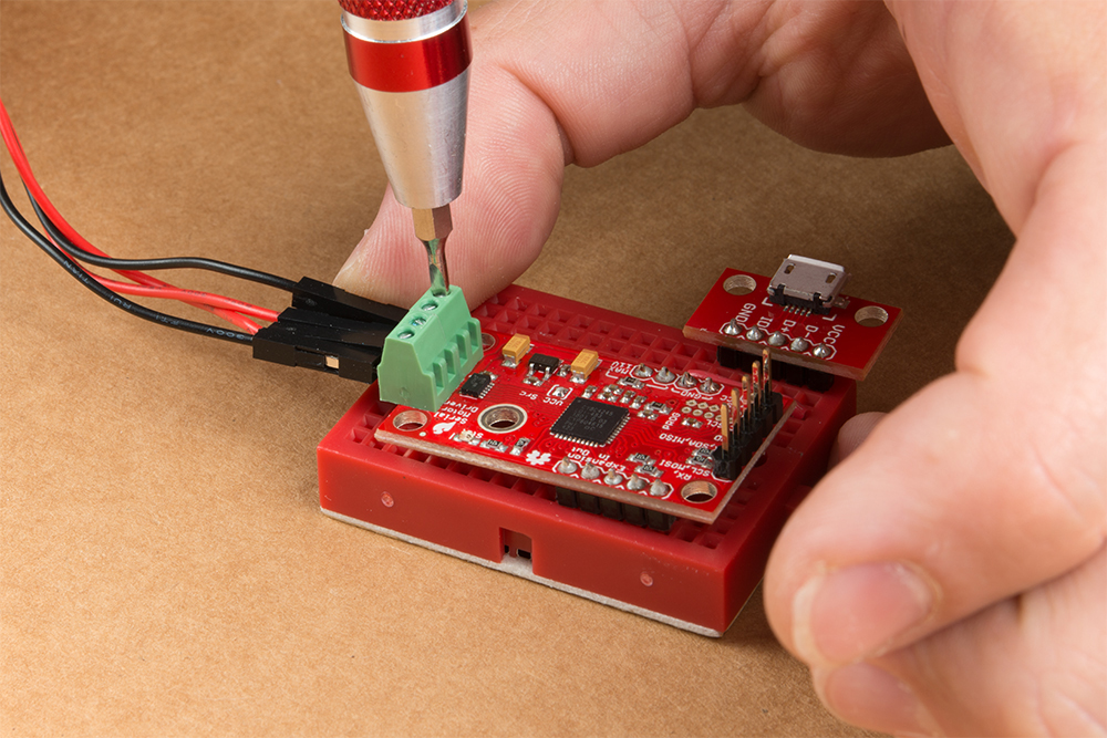
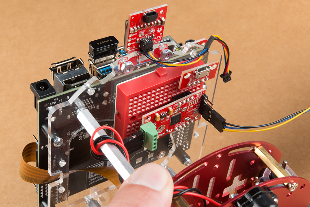
Utilize a small flat head screwdriver to loosen the four connection points on the screw terminals. When inserting the motor connection wires, note the desired output given the caution noted in section #1 of this assembly guide.
Note from section #1: Do not worry about the motor orientation as you will determine proper motor operation in how you connect the motor leads to the SparkFun Serial Controlled Motor Driver.
These connection points can be corrected when testing the robot functionality. If your Jetbot goes straight when you expect Jetbot to turn or vice versa, your leads need to be corrected.
Set this assembly aside for full installation later.
4. Accessory Installation to Main Chassis
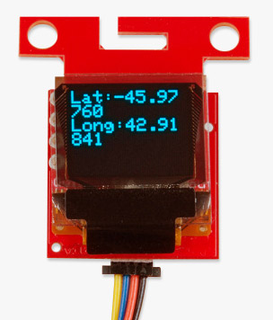
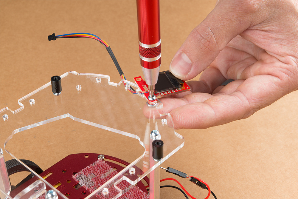
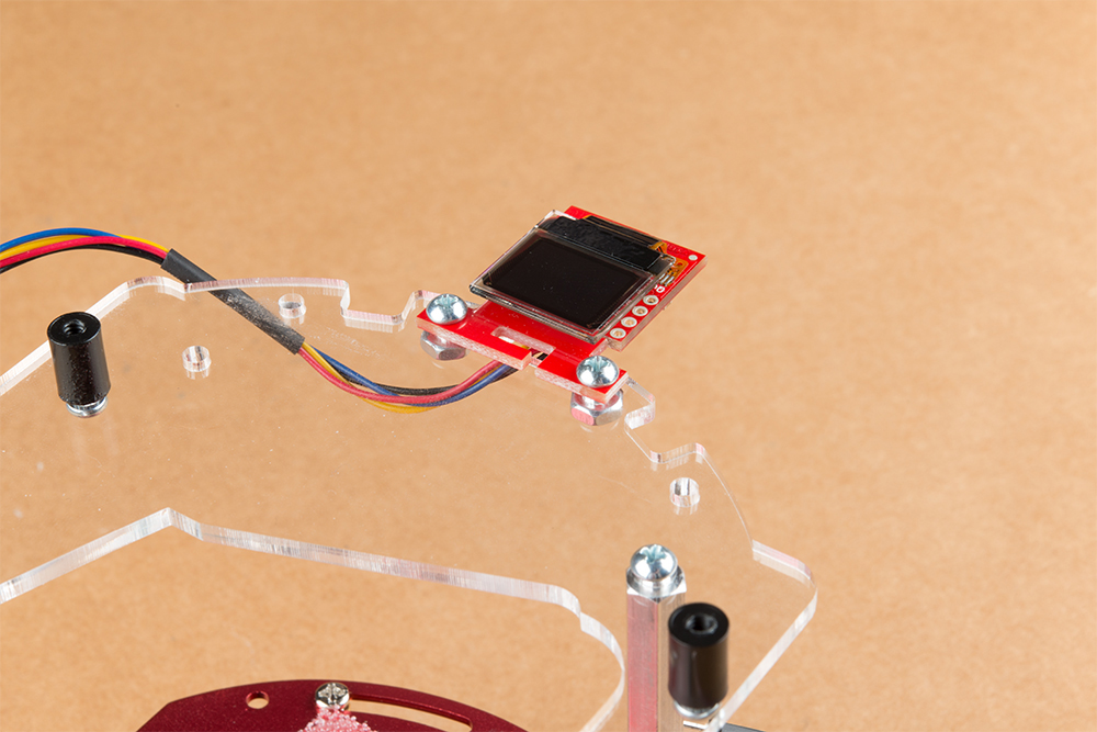
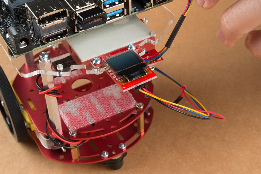
Align the mounting holes on the SparkFun Micro OLED (Qwiic) with those on the back of the SparkFun Jetbot acrylic mounting plate. Install the Micro OLED using two 1/4 in 4-40 Phillips head screws and two 4-40 machine screw nuts.
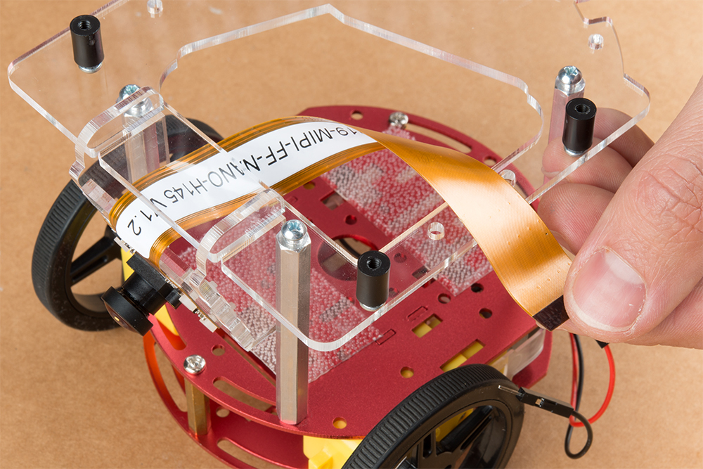
Thread the ribbon cable of the Leopard imaging camera back through the acrylic mounting plate and half-helix towards the left side of the Jetbot.
Install the Jetson Nano Dev kit to the nylon standoffs using four 1/4 in 4-40 Phillips head screws. Tighten each screw slightly in a criss-cross pattern to ensure the through holes do not bind during install until finger tight. Make sure you can still access the camera ribbon cable.
Note: the camera connector is made from small plastic components & can break easier than you think. Please be careful with this next step.
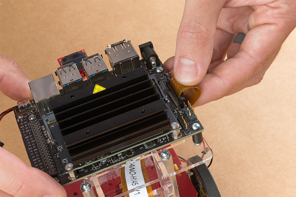
Loosen the camera connector with a fingernail or small flathead screwdriver. Fit the ribbon cable into this connector and depress the plastic press fit piece of the connector to hold the ribbon cable in place.
Unpackage & install the USB Wifi adaptor into one of the USB ports on the Jetson nano Dev Kit. The drivers for this Wifi adaptor are pre-installed on the SparkFun Jetbot image. If you are making your own image, you will need to ensure you get these from Edimax.
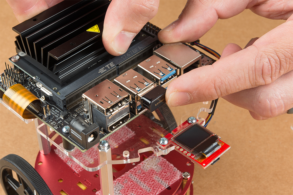
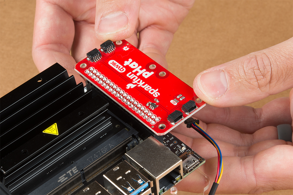
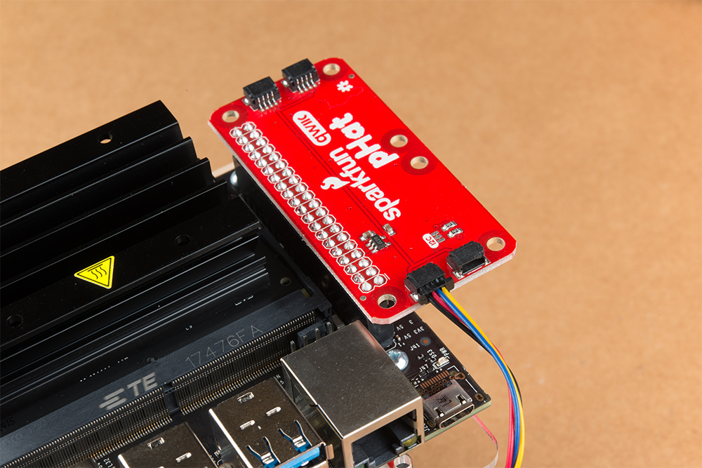
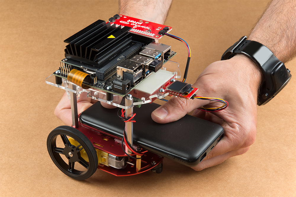
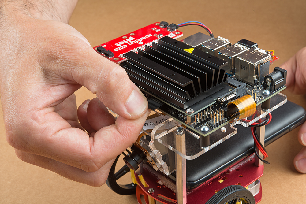
Align the SparkFun pHat with the GPIO headers on the Jetson Nano Dev Kit so that the pHat overhangs the right hand side of the Jetbot. For additional information on hardware assembly of the SparkFun pHat, please reference the hookup guide here.
Note: The heatsink on the Jetson Nano Dev Kit will only allow for one orientation of the SparkFun pHat.
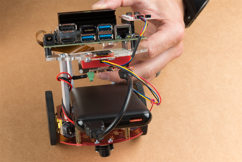
Wrap the motor wires around the rear/left standoff to take up some of the slack; one or two passes should do. Peel the cover off the self adhesive backing on the mini breadboard you set aside at the end of section #3.
Place the breadboard near the back of the Jetbot Acrylic mounting plate where there is good adhesion & access to all the components. Attach the (4-pin) Female Jumper Qwiic cable to the SparkFun Serial Controlled Motor Driver pins as shown. Yellow to ”SCL,” Blue to ”SDA,” Black to ”GND.”
Daisy chain the polarized Qwiic connector on the other end of the (4-pin) Female Jumper Qwiic cable into the back of the SparkFun Micro OLED (Qwiic).
Using the 100mm Qwiic Cable attach the SparkFun Micro OLED front Qwiic connector to the SparkFun pHat as shown.
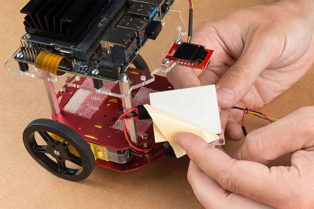
Cut the Dual Lock Velcro into two pieces and align them on the 10Ah battery & top plate of the Two-Layer Circular Robotics Chassis as shown below. Ensure that the USB ports on the battery pack are pointing out the back of the Jetbot. Additionally, the orange port (3A) will need to power the Jetson Nano Dev Kit & therefore will need to be on the right side of the Jetbot.
Apply firm pressure to the battery pack to attach to the Jetbot chassis via the Dual Lock Velcro.
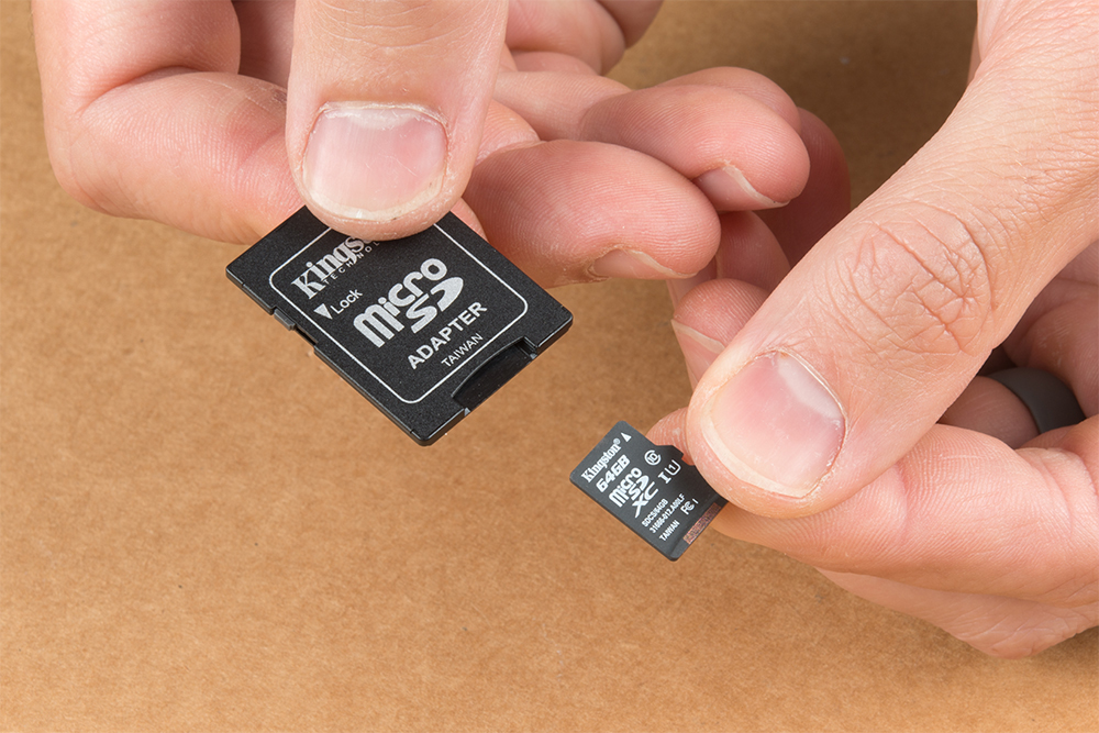
Remove the micro SD card from the SD card adapter.
Insert the micro SD card facing down into the micro SD card slot on the front of the Jetson Nano Dev Kit. Please see the next three pictures for additional details.
The USB ports on the back of the 10Ah battery pack has two differently colored ports. The black port (1A) is used to power the motor driver via the SparkFun microB breakout. Utilize one of the 6 in micro-B USB cables to supply power to the microB breakout.
Note: Once you plug the Jetson Nano Dev Kit into the 3A power port, this will ”Boot Jetson Nano” which is not covered in detail until the links in section #5 of this assembly guide. Do not proceed unless you are ready to move forward with the software setup & examples provided by NVIDIA.
The orange port (3A) is used to power the Jetson Nano Dev Kit. Utilize the remaining 6 in micro-B USB cable to supply power to the Jetson Nano Dev Kit.
Congratulations! You have fully assembled your SparkFun JetBot AI Kit!
5. Software Setup Guide from NVIDIA
Attention: The SD card in this kit comes pre-flashed to work with our hardware and has the all the modules installed (including the sample machine learning models needed for the collision avoidance and object following examples). The only software procedures needed to get your Jetbot running are steps 2-4 from the Nvidia instructions (i.e. setup the WiFi connection and then connect to the Jetbot using a browser). Please DO NOT format or flash a new image on the SD card; otherwise, you will need to flash our image back onto the card (instructions below).
Your SparkFun Jetbot comes with a Pre-Flashed micro SD card. Users only need to plug in the SD card and set up the WiFi connection to get started.
The default password on everything (i.e. login/user, jupyter notebook, and superuser) is ”jetbot”.
We recommend that users change their passwords after initial setup. These are typically covered on the first boot of your Jetson Nano as detailed in the NVIDIA Getting Started with Jetson Nano walkthrough
Software Setup
The only steps needed to get your Jetbot kit up and running is to log into the Jetbot and setup your WiFi connection. Once that is done, you are now ready to connect to the Jetbot wirelessly. If you need instructions for doing so, you can use the link below.However, please take note of our instructions below. You will want to skip steps 1 and 5 to avoid erasing the image on the card or undoing the hardware configuration.NVIDIA JETBOT WIKI SOFTWARE SETUP
Instructions
Skip step 1 of Nvidia’s instructions: It references how to flash your SD card, so feel free to skip to Step 2 – Boot Jetson Nano.
Note: Following Step 1 will erase the pre-flashed image and make a lot of extra work for yourself.
Skip step 5 of Nvidia’s instructions: This step should already be setup on the pre-flashed SD card.
If in the future, you need to update your notebooks, make sure that if you are following Step 5 – Install latest software (optional), skip the last command line instruction of the forth step.
Get and install the latest JetBot repository from GitHub by entering the following commands
COPY CODEgit clone https://github.com/NVIDIA-AI-IOT/jetbot
cd jetbot
sudo python3 setup.py install
Note:Running sudo python3 setup.py install in the command line will overwrite the software modifications for SparkFun’s hardware in the kit.
Troubleshooting
In the event that you accidentally missed the instructions above, here are instructions to get back on track.
Re-Flashing the SD card
If you need to re-flash your SD card, follow the instructions from Step 1 Nvidia’s guide. However, download and use our image instead (click link below).DOWNLOAD SPARKFUN’S JETBOT IMAGENote: Don’t forget to uncompress (i.e. unzip, extract, or expand) the file from the .zip file/folder first. You should be pointing the ”flashing” software to an ~62GB .img file to flash the image (sparkfun_jetbot_v01-00.img) onto the SD card.
Alternatively, there are other options for flashing images onto an SD card. If you have a preferred method, feel free to use the option you are most comfortable with.
Re-Applying the Software Modifications
If you have accidentally, overwritten the software modifications for the hardware included in your kit, you will need to repeat Step 5 from Nvidia’s guide from the desktop interface (if you are comfortable performing the following steps from the command line, feel free to do so).
Skip steps 1 and 2: Plug in a keyboard, mouse, and monitor. Then log in to the desktop interface (if you haven’t changed your password, the default password is: jetbot).
Follow step 3: Launch the terminal. There is an icon on sidebar on the left hand side. Otherwise, you can use the keyboard short cut (Ctrl + Alt + T).
Follow step 4: However, before you execute sudo python3 setup.py install you will want to copy in our file modifications to the jetbot directory you are in.
Begin by downloading our files (click link below).
Next, replace the files in the jetbot folder. The file paths must be the same, so make sure to overwrite files exactly.
Click on the icon that looks like a filing cabinet on the left hand side of the GUI. This is your Home directory. From here, you will need to proceed into the jetbot folder. There you will find a jetbot folder with similar files to the ones you just extracted. Delete the folder and copy in our files (you can also just overwrite the files as well).
Now, you can execute sudo python3 setup.py install in the terminal.
Follow step 5: Finish up by following step 5. Now you are back on track to getting your Jetbot running again!
6. Examples
The ”object following” jupyter notebook example won’t work due to the required dependencies that had not been released by NVIDIA prior to the creation of the SparkFun JetBot image. These updates can be manually installed on your Jetson Nano with the JetPack 4.2.1 release.
Update: The engine generated for the example utilized a previous version of TensorRT and is therefore, not compatible with the latest release. For more details on this issue, check out the following GitHub issue.NVIDIA JETBOT WIKI EXAMPLES
Resources and Going Further
Now that you’ve successfully got your JetBot AI up and running, it’s time to incorporate it into your own project!
For more information, check out the resources below:
Need some inspiration for your next project? Check out some of these related tutorials:
Easy Driver Hook-up Guide
Get started using the SparkFun Easy Driver for those project that need a little motion.
Servo Trigger Hookup Guide
How to use the SparkFun Servo Trigger to control a vast array of Servo Motors, without any programming!
SparkFun 5V/1A LiPo Charger/Booster Hookup Guide
This tutorial shows you how to hook up and use the SparkFun 5V/1A LiPo Charger/Booster circuit.
Wireless Remote Control with micro:bit
In this tutorial, we will utilize the MakeCode radio blocks to have the one micro:bit transmit a signal to a receiving micro:bit on the same channel. Eventually, we will control a micro:bot wirelessly using parts from the arcade:kit!
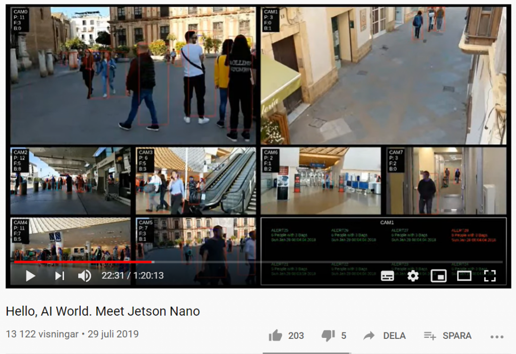
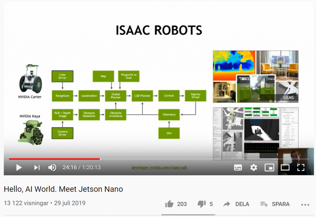
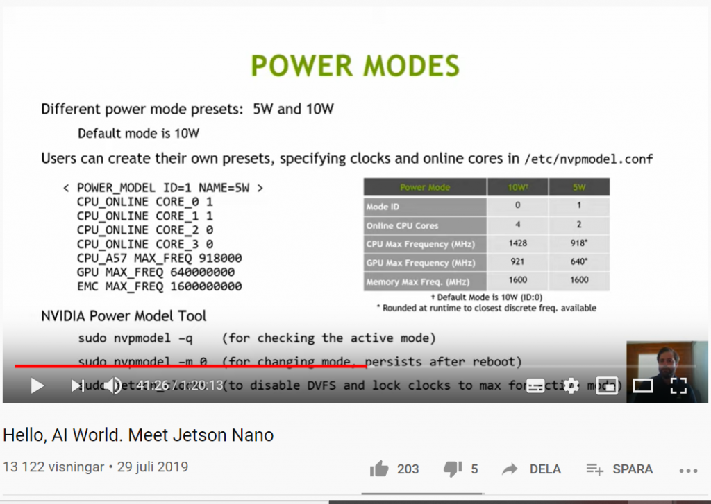
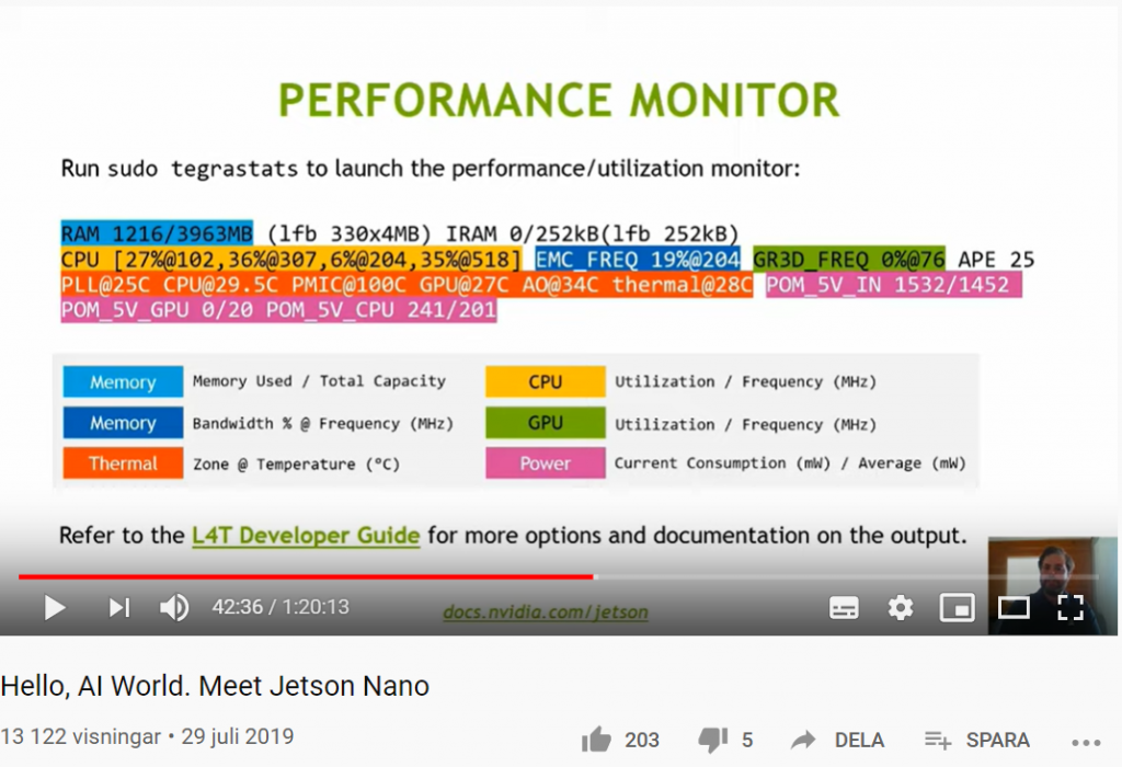
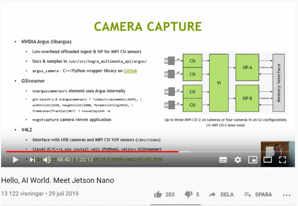
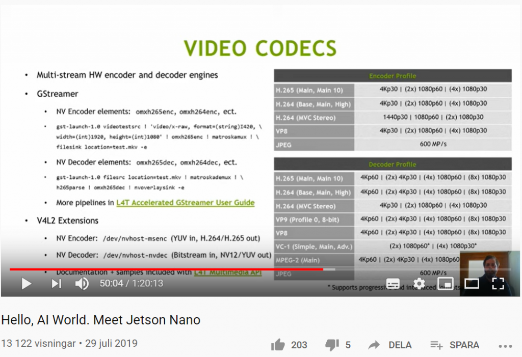
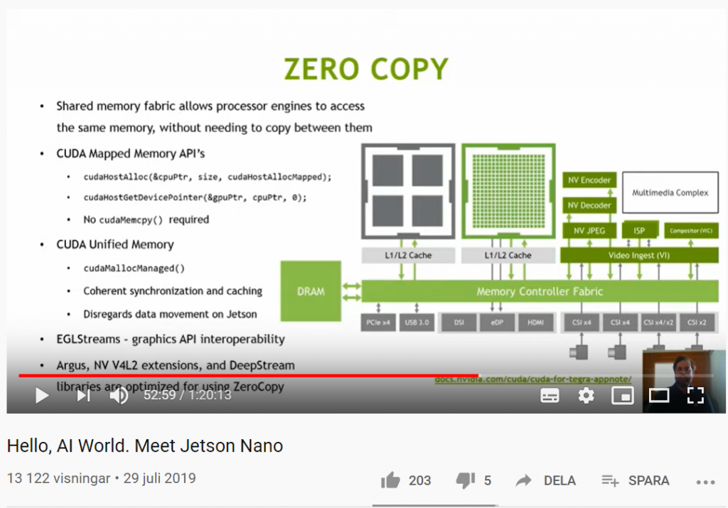
Join us for this engaging, informative webinar and live Q&A session to find out more about the hardware and software behind Jetson Nano. See how you can create and deploy your own deep learning models along with building autonomous robots and smart devices powered by AI. Find more resources for Jetson Nano at https://developer.nvidia.com/embedded…
Maskininlärning (Machine Learning, ML) representerar ett nytt paradigm i programmering, där du istället för att programmera explicita regler på ett språk som Java eller C ++, bygger ett system som tränas och lärs upp på data från ett stort antal exempel, för att sedan kunna dra slutsatser av ny data baserat på de mönster som identifierats utifrån träningsdatat. Men hur ser ML egentligen ut? I del ett av Machine Learning Zero to Hero går AI-evangelisten Laurence Moroney (lmoroney @) genom ett grundläggande Hello World-exempel på hur man bygger en ML-modell och introducerar idéer som vi kommer att tillämpa i det senare avsnittet om datorseende (Computer Vision) längre ner på denna sida. Vill du ha en lite mer omfattande introduktion rekommenderar jag Introduction to TensorFlow 2.0: Easier for beginners, and more powerful for experts.
Prova själv den här koden i Hello World of Machine Learning: https://goo.gle/2Zp2ZF3
Basic Computer Vision with ML (ML Zero to Hero, part 2)
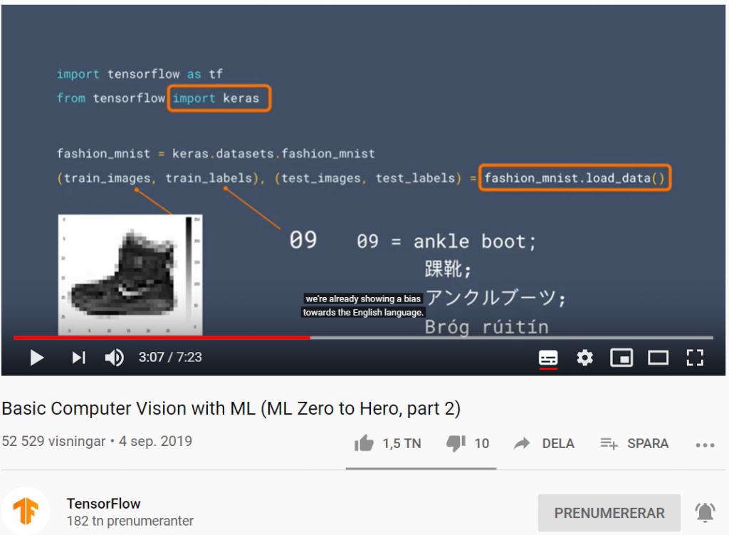
I del två av Machine Learning Zero to Hero går AI-evengalisten Laurence Moroney (lmoroney @) genom grundläggande datorseende (Computer Vision) med maskininlärning genom att lära en dator hur man ser och känner igen olika objekt (Object Recognition).
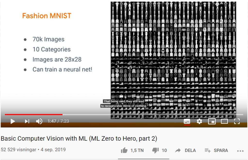
Fashion MNIST – ett dataset med bilder på kläder för benchmarking
Fashion-MNIST är ett forskningsprojekt av Kashif Rasul & Han Xiao i form av ett dataset av Zalandos artikelbilder. Det består av ett träningsset med 60 000 bildexempel och en testuppsättning med 10 000 exempel. Varje exempel är en 28 × 28 pixlar stor gråskalabild, associerad med en etikett från 10 klasser (klädkategorier). Fashion-MNIST är avsett att fungera som en direkt drop-in-ersättning av det ursprungliga MNIST-datasättet för benchmarking av maskininlärningsalgoritmer.
Fashion MNIST dataset
Varför är detta av intresse för det vetenskapliga samfundet?
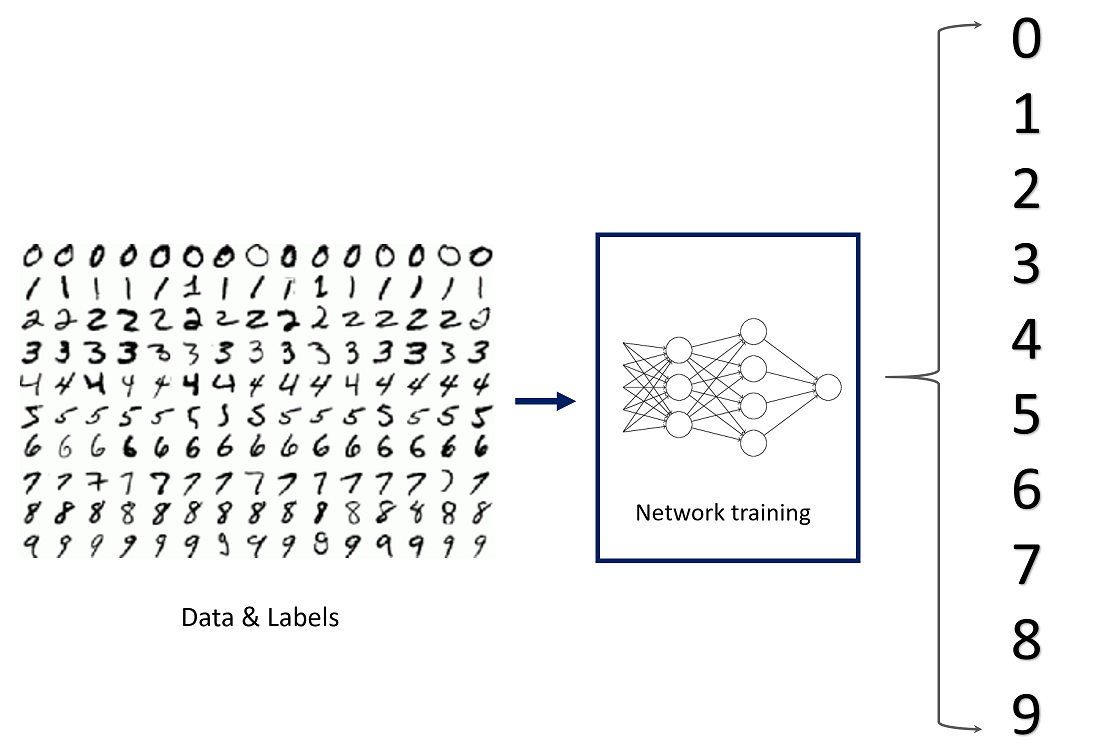
Det ursprungliga MNIST-datasättet innehåller många handskrivna siffror. Människor från AI / ML / Data Science community älskar detta dataset och använder det som ett riktmärke för att validera sina algoritmer. Faktum är att MNIST ofta är det första datasetet de provar på. ”Om det inte fungerar på MNIST, fungerar det inte alls”, sägs det. ”Tja, men om det fungerar på MNIST, kan det fortfarande misslyckas med andra.”
MNIST Dataset för nummerklassificering
Fashion-MNIST är avsett att tjäna som en direkt drop-in ersättning för det ursprungliga MNIST-datasetet för att benchmarka maskininlärningsalgoritmer, eftersom det delar samma bildstorlek och strukturen för tränings- och testdelningar.
Varför ska man ersätta MNIST med Fashion MNIST? Här är några goda skäl:
Se mer om att koda TensorFlow → https://bit.ly/Coding-TensorFlow Prenumerera på TensorFlow-kanalen → http://bit.ly/2ZtOqA3
Introducing convolutional neural networks (ML Zero to Hero, part 3)
I del tre av Machine Learning Zero to Hero diskuterar AI-evangelisten Laurence Moroney (lmoroney @) CNN-nätverk (Convolutional Neural Networks) och varför de är så kraftfulla i datorseende-scenarier. En ”convolution” är ett filter som passerar över en bild, bearbetar den och extraherar funktioner eller vissa kännetecken (features) i bilden. I den här videon ser du hur de fungerar genom att bearbeta en bild för att se om du kan hitta specifika kännetecken (features) i bilden.
Codelab: Introduktion till invändningar → http://bit.ly/2lGoC5f
Introducing convolutional neural networks (ML Zero to Hero, part 3)
Build an image classifier (ML Zero to Hero, part 4)
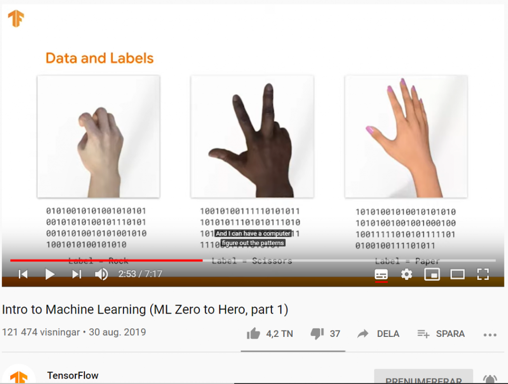
I del fyra av Machine Learning Zero to Hero diskuterar AI-evangelisten Laurence Moroney (lmoroney @) byggandet av en bildklassificerare för sten, sax och påse. I avsnitt ett visade vi ett scenario med sten, sax och påse, och diskuterade hur svårt det kan vara att skriva kod för att upptäcka och klassificera dessa. I de efterföljande avsnitten har vi lärt oss hur man bygger neurala nätverk för att upptäcka mönster av pixlarna i bilderna, att klassificera dem, och att upptäcka vissa kännetecken (features) med hjälp av bildklassificeringssystem med ett CNN-nätverk (Convolutional Neural Network). I det här avsnittet har vi lagt all information från de tre första delarna av serien i en.
Colab anteckningsbok: http://bit.ly/2lXXdw5
Rock, papper, saxdatasätt: http://bit.ly/2kbV92O
Build an image classifier (ML Zero to Hero, part 4)